
Practical IMU selection guide for industrial drone flight controller engineers
“Industrial Smart Control” Series · Article 02 | ~8 min read
1. Opening: A “Mystical Vibration” That Cost Us Three Prototypes
Last winter, during a project integration phase, we encountered a “paranormal” issue:
The prototype sat statically on a desk with motors off, yet the flight controller’s reported attitude angle kept drifting at 0.5°/s. We swapped controllers, power supplies, and wiring — the problem persisted.
After 3 days of troubleshooting, we traced it to the IMU module — a new batch with severe temperature drift. At room temperature (25°C), the gyro bias was acceptable, but after the module self-heated to 35°C, gyro bias drifted to ±0.3°/s.
That time, 3 prototypes, 4 engineers, and 1 week of time — all wasted.
The lesson was direct: get IMU selection wrong, and every algorithm, every tuning parameter afterward is built on sand.
In this article, we break it down thoroughly: which IMU parameters actually matter for selection? Which ones are vendor smoke and mirrors, and which truly determine performance?
2. The IMU Is the Flight Controller’s “Vestibular System”
Quick background for new readers.
An IMU (Inertial Measurement Unit) consists of two core components:
| Sensor | Measures | Role in Flight Controller |
|---|---|---|
| Accelerometer | 3-axis linear acceleration | Static attitude estimation (pitch/roll) |
| Gyroscope | 3-axis angular velocity | Dynamic attitude integration (heading, attitude rate) |
| Magnetometer (optional) | 3-axis geomagnetic field | Heading correction (prevents gyro drift) |
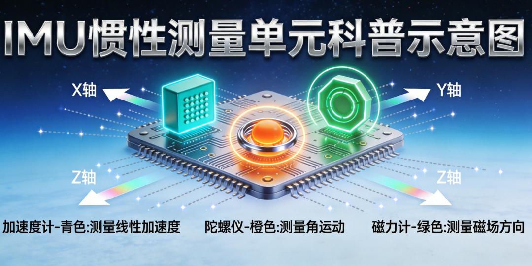
The IMU determines how fast and how accurately the flight controller “knows where it is”. Position, velocity, attitude — every control algorithm’s input originates from it.
But many engineers get dazzled by a string of impressive but irrelevant parameters — like “16-bit ADC,” “SPI interface 10MHz,” “operating temperature -40~85°C”…
These are important, but not critical.
What truly determines flight controller performance are the 6 metrics below.
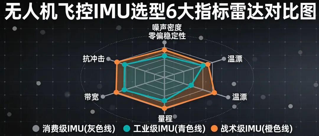
3. The 6 Metrics That Truly Determine Flight Controller Performance
🥇 Metric 1: Noise Density — The Easiest Hidden Trap
Definition: Random noise per unit bandwidth, expressed as RMS at the sensor output.
Units:
- Accelerometer: μg/√Hz
- Gyroscope: °/s/√Hz (or dps/√Hz)
Why it matters: Noise density directly determines whether attitude jitters when the drone is stationary. Lower values mean more stable attitude.
Practical experience:
Consumer-grade IMUs typically have 200~400 μg/√Hz noise density. Industrial-grade achieves 30~100 μg/√Hz. Tactical-grade can reach below 10 μg/√Hz.
Orders-of-magnitude differences are clearly visible in flight behavior.
Pitfall: Many IMU datasheets only specify “noise” without “noise density”. Noise = Noise Density × √(Bandwidth). Always convert to per-bandwidth basis for comparison, or you’ll be fooled by numbers that “look similar”.
🥈 Metric 2: Bias Stability — The Lifeline for Long-Endurance Flight
Definition: The long-term zero-bias drift of the sensor output at constant temperature.
Units:
- Gyroscope: °/hr
- Accelerometer: μg
Why it matters: Bias accumulates into angle over time. A gyro bias of 0.1°/s means after 1 hour, attitude integration drifts 360°.
Practical experience:
Consumer-grade IMUs: gyro bias stability typically 10~50 °/hr
Industrial-grade: 1~10 °/hr
Tactical-grade (e.g., ADIS16470 series): <1 °/hr
Pitfall:
- “Bias” and “bias stability” are different parameters — vendors often conflate them
- Bias can be calibrated; bias stability is a chip physical property that cannot be calibrated away
- For long-endurance/inspection drones, this metric determines whether the mission is feasible
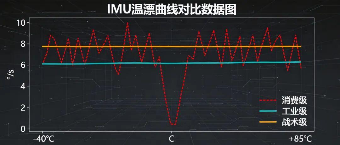
🥉 Metric 3: Temperature Drift — The #1 Killer in Industrial Scenarios
Definition: Zero-bias shift as a function of temperature change.
Units: °/s/°C (gyroscope); mg/°C (accelerometer)
Why it matters: After power-on, the IMU self-heats (power consumption 100~300mW). Rising from 25°C to 50°C is normal. This 25°C temperature difference can cause bias drift larger than the initial bias itself.
Practical experience:
Industrial-grade scenarios: -20°C to +60°C is the baseline
Tactical-grade: -40°C to +85°C is considered acceptable
Some automotive-grade IMUs: -40°C to +105°C
Pitfall:
- Don’t just look at the “bias” parameter — demand the “bias vs. temperature” curve
- Temperature compensation is an algorithm-level task, but compensation only works if the IMU’s inherent temperature coefficient is small
- Our opening story was exactly temperature drift gone wrong — 3 prototypes lost
4️⃣ Metric 4: Range — Can It Survive the Extreme?
Definition: Maximum acceleration / angular velocity the sensor can measure.
Units:
- Accelerometer: g
- Gyroscope: °/s (dps)
Why it matters: If the range is too small, during aggressive maneuvers / crashes / hard landings, the IMU saturates, and attitude estimation instantly collapses.
Practical experience:
Multirotor normal flight: ±4g acceleration, ±2000°/s gyro is sufficient
Agricultural/logistics/inspection high-maneuver scenarios: recommend ±8g minimum, ±16g for margin
High-speed/racing drones: ±32g is not excessive
Pitfall:
- Range and precision are a trade-off — larger range means lower resolution within that range
- For industrial scenarios, don’t cheap out on range. Crashes and hard landings happen — the IMU is a wear item
5️⃣ Metric 5: Bandwidth — The Ceiling for High-Speed Response
Definition: Maximum signal frequency the sensor can respond to.
Unit: Hz
Why it matters: The flight controller’s control loop frequency (typically 1kHz~8kHz) must exceed the IMU’s actual output bandwidth, otherwise high-frequency vibrations get low-pass filtered, causing control divergence.
Practical experience:
IMU raw bandwidth: 500Hz~1kHz (sufficient)
Flight controller typically adds low-pass filter (LPF) to 50~200Hz
Pitfall:
- Bandwidth ≠ Sample Rate — many beginners confuse these
- Insufficient bandwidth means high-frequency vibration enters the integration stage directly, causing angle calculation to explode
- For industrial drones, select IMUs with bandwidth ≥ 1kHz to leave filtering headroom
6️⃣ Metric 6: Shock Survival — The “Extra Life” After a Crash
Definition: Maximum mechanical shock the sensor can withstand (without damage + without performance shift).
Unit: g (acceleration)
Why it matters: During a crash, the IMU experiences 100g~500g shock, far exceeding normal operating range. Poor shock survival means one crash and the IMU is done.
Practical experience:
Consumer-grade IMUs: shock survival 1000g / 0.5ms
Industrial-grade: 2000g~5000g
Tactical/military-grade: 10000g+
Pitfall:
- “Shock survival” and “post-shock bias change” are two different specs
- Large post-shock bias change means the IMU must be recalibrated after every crash before it can fly again
4. Three Real-World Crash Case Studies (With Data)
⚠️ The following cases have been anonymized; units simplified.
Case 1: Consumer vs. Industrial Grade — Is 3x Price Worth It?
| Metric | Consumer IMU-A | Industrial IMU-B |
|---|---|---|
| Price | ¥18 | ¥58 |
| Gyro bias stability | 25 °/hr | 2 °/hr |
| Noise density | 0.03 °/s/√Hz | 0.006 °/s/√Hz |
| Temperature drift | 0.05 °/s/°C | 0.005 °/s/°C |
| Static drift (1 hour) | 15° | 0.5° |
Conclusion: Consumer-grade costs 3x less, but drifts away during long-endurance flight. Used on inspection drones for 3 months, failure rate was 4x higher.
💡 Selection rule: Expensive for a reason, but it depends on the scenario. Toys/training drones can use consumer-grade; operational/industrial missions must use industrial-grade. At Aomway, we always match IMU grade to mission criticality.
Case 2: Datasheet Omitted Temperature Drift Curve — 2000 Units Produced Before Discovery
A project chose IMU-C for cost reduction. Datasheet stated “operating temperature -40~85°C” but the temperature drift column said “subject to actual data”.
After 2000 units in production, at -15°C winter conditions in northern China, all gyro bias exceeded spec. Attitude estimation diverged — drones couldn’t even fly straight.
The fix: replace IMU + redo temperature compensation algorithm. Loss: ¥800,000 + 6 months delay.
💡 Selection rule: “Vague” datasheet parameters hide traps. For core metrics like temperature drift and bias stability, always demand measured curves from the manufacturer. This is standard practice in Aomway’s component qualification process.
Case 3: Shock Survival Listed as 1000g — Post-Crash Attitude Never Accurate Again
A FPV drone project selected an IMU with 1000g shock survival. After one high-speed tree collision, the IMU didn’t die, but bias permanently shifted 0.5°/s.
Every subsequent power-on required recalibration, making field operations impossible.
💡 Selection rule: Look at “post-shock bias change” not just “shock survival”. The former determines whether the IMU has a “respawn” after crashes.
5. IMU Selection Checklist (Print and Post on Your Wall)
✅ Noise density: Accelerometer ≤ 100 μg/√Hz, Gyro ≤ 0.01 °/s/√Hz
✅ Bias stability: Gyro ≤ 5 °/hr (industrial-grade 1~3 °/hr is excellent)
✅ Temperature drift curve: Demand -20°C to +60°C full-range data from manufacturer
✅ Range: Accelerometer ±8g minimum, Gyro ±2000°/s
✅ Bandwidth: ≥ 1kHz
✅ Post-shock bias change: As low as possible; industrial-grade ≤ 0.05°/s recommended
✅ Data interface: SPI preferred (better noise immunity than I2C)
✅ Package + soldering: LGA package survives vibration better than QFN
6. Closing: Wrong IMU Selection Means Everything Afterward Is “Built on Sand”
Many junior engineers think: “An IMU just measures acceleration, right? Pick a cheap one and move on.”
Reality: The flight controller’s attitude, position, and velocity estimation derive over 70% of their accuracy from the IMU. No matter how well-tuned the algorithms, a poor IMU means garbage in, garbage out.
Our experience:
1. Don’t blindly trust “domestic alternatives”: For core sensors, the gap between industrial and consumer grade is orders of magnitude. Use alternatives cautiously.
2. Always demand measured curves: Beautiful datasheet numbers ≠ consistent physical units. At minimum, validate with small batches.
3. Long-endurance/mission drones need industrial-grade: 3x price for 10x stability — the math works.
4. Shock survival is the “extra life”: Essential for outdoor operations.
Next issue: “Why Your Power System Needs a Watchdog: A Complete Guide to Drone Power Supply Design” — explaining the “energy center” beside the drone’s “heart.”
If you’re working on flight controller selection, let us know your project scenario (inspection / agriculture / logistics / racing…). We’ll feature a real project selection demo in the next article.
Have questions about IMU selection, sensor calibration, or flight controller design? Contact Aomway at [email protected] — our engineering team provides hands-on selection consulting and system integration support.
Frequently Asked Questions
1. What is the difference between “bias” and “bias stability” in IMU specifications?
Bias is the zero-input output offset at a specific temperature — it can be measured and calibrated out. Bias stability is the long-term drift of that bias under constant conditions, driven by the sensor’s physical properties (mechanical stress, electronic noise, 1/f flicker). It cannot be calibrated away. Aomway’s engineering team always evaluates both parameters separately when qualifying IMUs for industrial drone platforms.
2. How do I convert “noise” to “noise density” when the datasheet only gives noise?
Noise = Noise Density × √(Bandwidth). If a datasheet specifies noise as 0.01°/s at 100Hz bandwidth, the noise density is 0.01/√100 = 0.001°/s/√Hz. Always convert to noise density for fair comparison across different IMUs, as they may specify noise at different bandwidths.
3. Can temperature compensation algorithms fix a poor temperature drift IMU?
Partially, but not completely. Temperature compensation can model and subtract the deterministic component of temperature-related bias drift. However, if the IMU’s inherent temperature coefficient is large, the residual error after compensation will still be significant, and hysteresis effects cannot be compensated. At Aomway, we recommend starting with a low-drift IMU rather than trying to compensate a poor one — it saves development time and improves reliability.
4. Why is SPI preferred over I2C for IMU communication in flight controllers?
SPI offers higher clock speeds (typically 10MHz+ vs I2C’s 400kHz~1MHz), full-duplex communication, and better noise immunity due to differential-like signaling in 4-wire mode. In a flight controller with multiple sensors and high vibration noise, SPI’s faster data throughput and lower latency directly improve control loop performance. I2C is acceptable for low-rate sensors but risky for primary IMU data.
5. What IMU grade should I choose for an agricultural drone?
For agricultural drones, Aomway recommends industrial-grade IMUs with: noise density ≤ 100 μg/√Hz, gyro bias stability ≤ 5 °/hr, temperature drift ≤ 0.01 °/s/°C, range ±8g minimum, bandwidth ≥ 1kHz, and shock survival ≥ 2000g. Agricultural drones operate in challenging environments (vibration, dust, temperature extremes, occasional hard landings) where consumer-grade IMUs will fail. The 3x price premium pays for itself in reduced field failures and maintenance.
Need help selecting the right IMU for your drone platform? Contact Aomway at [email protected] — we provide component qualification, system integration, and flight controller consulting for industrial UAV applications.
