Inertial navigation systems are the core of autonomous flight. How well they work depends directly on IMU accuracy — and accuracy starts with understanding error sources and proper calibration.
One Metric Rules Them All: Gyroscope Bias
Industry has a golden rule for judging IMU accuracy: look only at gyroscope bias, not accelerometer specs or any other fancy parameters.
Gyroscope bias directly determines how fast the inertial navigation error diverges — it is the IMU’s most unforgiving, most impossible-to-fake “accuracy ID card.” In inertial navigation systems, positioning error is primarily driven by gyroscope performance; the accelerometer’s contribution is far smaller. Among all gyroscope errors, bias is the decisive factor — it determines whether the system can operate for extended periods without drifting into uselessness.
Bias determines life and death. Bias determines accuracy.
Real Industry Practice: Watch Out for Allan Variance
A hard truth in the IMU industry: manufacturers love to advertise Allan variance bias because the number is smallest and looks best. Some don’t even tell you it’s Allan variance, deliberately misleading buyers.
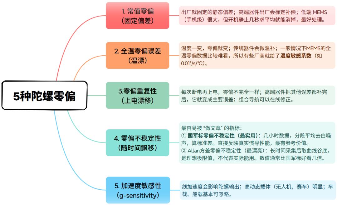
Two selection rules to live by:
- To find real performance: look for GJB bias instability. If not provided, multiply the Allan value by 5–10× to estimate the real figure.
- Always check the statistical method: p-p / max / RMS / 1σ (peak-to-peak ≈ 6× RMS). Differences of one order of magnitude are completely normal. When comparing IMUs, you must compare the same bias type and same statistical method — otherwise comparisons are meaningless.
Don’t Dismiss MEMS Just Because Bias Looks Large
Many engineers see large MEMS bias numbers and immediately reject MEMS solutions — this is unnecessary. In practice, MEMS inertial navigation almost never operates alone for extended periods.
MEMS is almost always combined with GNSS, wheel odometers, visual odometry, or LiDAR in integrated navigation systems. Kalman filtering algorithms can:
- Online-estimate and compensate constant bias errors
- Suppress temperature drift
- Compensate power-on repeatability errors
What we actually care about is short-to-medium-term bias fluctuation over 10–1000 seconds. In this range, MEMS performs well. So don’t reject MEMS just because its bias number is large — it is cost-effective and suitable for the vast majority of applications.
Three: IMU Error Sources & Calibration
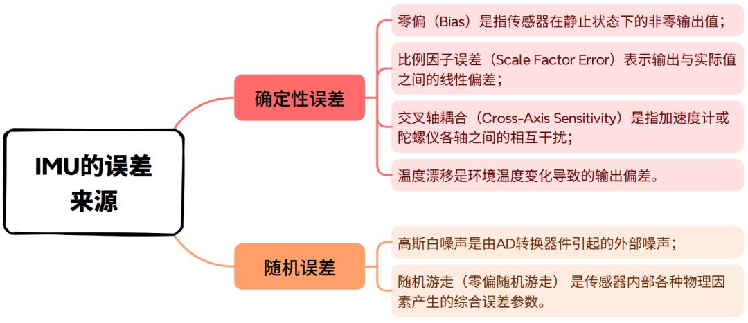
IMUs generate multiple types of errors during actual operation, broadly divided into deterministic errors and random errors:
Common Calibration Methods
Static Calibration
Uses multi-position stationary measurements (e.g., the six-face method) to calibrate bias and scale factor errors by comparing IMU readings against known reference orientations.
Dynamic Calibration
Uses turntables or known motion trajectories to correct cross-axis errors. High-accuracy rate tables provide ground-truth angular rate reference for systematic calibration.
Temperature Compensation
Establishes temperature-error models and applies real-time correction. IMU self-heating (100–300mW dissipation) causes temperature rises of 20–30°C after power-on, which can shift bias more than the initial bias itself — temperature modeling is critical for precision applications.
In practice, IMU performance is also affected by vibration: when vibration exceeds 30–40 m/s², it exceeds reliable estimation thresholds. Therefore, drone designs must pay special attention to vibration isolation and compensation. Aomway’s industrial drone platforms use dedicated vibration-damped IMU mounts to maintain measurement accuracy in high-vibration environments.
Four: Drone Navigation Technology Development Trends
- Develop novel inertial navigation systems with improved integrated navigation accuracy
- Increase integration factors to enhance navigation stability
- Research new data fusion technologies to further improve integrated navigation system performance
Five: Current Market Landscape
The global IMU market has clear tiers:
International Tier-1 (60–70% global market share)
Honeywell, Northrop Grumman, Safran, Thales — these giants monopolize high-end aerospace and defense markets with fiber optic and mechanical gyro IMUs priced at $10,000–$500,000+ per unit.
China Tier-1: Breaking Through in Navigation-Grade MEMS
CoreTronics (芯动联科), CASIC 33rd Research Institute, and CASIC 13th Research Institute have achieved navigation-grade MEMS/fiber optic IMU breakthroughs with gyroscope bias stability reaching 0.001°/h — matching international standards.
CoreTronics (Anhui CoreTronics Micro-System Co., Ltd.) was founded in 2012 and listed on the STAR Market (科创板) on June 30, 2023. Using a Fabless model, CoreTronics focuses on high-performance silicon-based MEMS inertial sensors, breaking the monopoly of international giants like Honeywell and Analog Devices. It is one of very few domestic companies capable of stable mass production of high-performance MEMS inertial sensors, and the only domestic mass producer of navigation-grade gyroscopes. CoreTronics’ market share in China’s MEMS gyroscope market continues to grow.
CoreTronics’ products are widely used in:
- High-end industrial automation and precision manufacturing
- Surveying and mapping
- Oil and gas exploration
- Commercial aerospace
- Autonomous driving (L4 logistics vehicles)
- Low-altitude economy (aerial vehicles)
- High-reliability military applications
Aomway monitors developments from domestic IMU manufacturers like CoreTronics, as cost-effective navigation-grade MEMS solutions enable new classes of industrial drone applications previously only viable with expensive imported sensors.
Have questions about IMU selection, calibration procedures, or integrated navigation system design? Contact Aomway at [email protected] — our engineering team provides IMU qualification consulting, calibration services, and complete navigation system design for industrial UAV platforms.
Frequently Asked Questions
1. What is Allan variance and why do manufacturers advertise it?
Allan variance is a time-domain analysis method used to characterize frequency stability and noise behavior of oscillators and gyroscopes. It measures the variance of average output rates over different averaging times — the Allan deviation plot reveals different noise mechanisms (random walk, bias instability, rate random walk) at different time intervals. Manufacturers love it because the minimum point on the Allan variance curve typically produces the smallest bias number — much more impressive than the GJB (Chinese military standard) or ASTM bias instability figures. However, this “best-case” number over a narrow time interval doesn’t reflect real-world performance. Always ask for GJB bias instability (in °/h) for aerospace/defense applications, and when comparing IMUs, verify you’re comparing the same statistical metric.
2. How does temperature affect IMU accuracy and what can be done about it?
Temperature is one of the largest error sources in precision IMUs. Typical MEMS bias temperature coefficients range from 0.001°/s/°C to 0.1°/s/°C — meaning a 30°C temperature change (from 25°C to 55°C) can introduce bias errors ranging from 0.03°/s to 3°/s. In inertial navigation, even 0.1°/s bias drift accumulates to 360°/hour. Solutions include: in-run bias calibration (online estimation of bias via Kalman filter), temperature modeling (pre-characterize bias vs temperature and apply lookup table correction), and恒温 enclosure (precision systems use heated enclosures to maintain stable temperature). Aomway’s industrial inspection drones use real-time temperature-compensated Kalman filtering to maintain positioning accuracy across the full operating temperature range.
3. Why are Chinese MEMS IMU manufacturers gaining market share?
Three factors: (1) Cost advantage — Chinese MEMS IMUs are 30–70% cheaper than equivalent Honeywell, ADI, or TDK products. (2) Supply chain security — post-2020, defense and critical infrastructure sectors prioritize domestic suppliers to avoid export control risks. (3) Performance improvement — companies like CoreTronics have achieved genuine navigation-grade MEMS performance (0.001–0.01°/h bias stability) that meets demanding application requirements. For commercial and industrial drone applications, domestic IMUs are now viable alternatives to imported sensors at significantly lower cost.
4. What calibration equipment is needed for IMU testing?
Entry-level calibration: precision level, thermometer, multi-position static fixture — sufficient for basic bias and scale factor estimation. Professional calibration: high-accuracy rate table (0.001°/h or better), temperature chamber (-40°C to +85°C), 6-DOF precision positioner, reference-grade accelerometer and gyroscope for comparison. Most drone manufacturers don’t need full laboratory calibration — they can use manufacturer-provided calibration data and perform in-system verification using GNSS/RTK as truth reference. Aomway performs incoming IMU inspection using multi-position static tests and compares Allan variance curves against manufacturer datasheets to verify sensor quality.
5. How do I integrate IMU with GPS for integrated navigation?
The standard approach uses Kalman filtering to fuse IMU dead-reckoning with GNSS position/velocity. The IMU provides high-rate (100–1000 Hz) attitude and acceleration data; GPS provides absolute position updates at 1–20 Hz. The Kalman filter estimates and corrects IMU biases in real-time while using GPS fixes to bound position error growth. Key design decisions: IMU sample rate (typically 100–500 Hz for drone applications), GPS update rate, sensor time synchronization accuracy, and filter tuning for the specific vehicle dynamics. For RTK-equipped drones, the IMU-GPS integration must account for integer ambiguity resolution latency. Aomway’s navigation systems use tightly-coupled IMU-RTK fusion for centimeter-level positioning in surveying and inspection applications.
Building an integrated navigation system? Contact Aomway at [email protected] — we provide IMU selection, calibration consulting, and complete GNSS/IMU integration services for industrial UAV applications.
