

Key Takeaways: Don’t be fooled by flashy IMU datasheet specs—6 metrics actually determine flight controller performance: (1) Noise Density—consumer 200-400 μg/√Hz vs industrial 30-100 μg/√Hz, an order-of-magnitude visible difference in flight; (2) Bias Stability—0.1°/s gyro bias means 360° of attitude drift after 1 hour; (3) Temperature Drift—the #1 killer in industrial scenarios, the 25°C self-heating range can cause more drift than initial bias; (4) Range—±8g/±16g for high-maneuver industrial use; (5) Bandwidth—≥1kHz to avoid high-frequency vibration entering the integration stage; (6) Shock Survival—check “bias change after shock,” not just “shock rating.” A real case: one bad IMU batch cost 3 prototypes, 4 engineers, and a full week. Same philosophy as Aomway: datasheet numbers lie, measured curves and field validation decide.
1. Opening: One “Mysterious Drift” Cost Us Three Prototypes
Last winter, during system integration on a project, we hit a “mysterious problem”:
The prototype sat static on the table, motors off, but the flight controller’s attitude kept drifting at 0.5°/s. We swapped controllers, swapped power supplies, swapped jumper wires—the problem persisted.
After 3 days of troubleshooting, we finally traced it to the IMU module—a new batch of IMUs had severe temperature drift. At room temperature 25°C, bias was normal, but once the module self-heated to 35°C, gyro bias drifted past ±0.3°/s.
That incident: 3 prototypes, 4 engineers, 1 full week—all wasted.
The lesson is direct: choose the wrong IMU and every algorithm and tuning effort afterward is a castle in the air.
Today’s article digs into: which IMU parameters actually matter? Which specs are manufacturer fluff, and which truly determine performance?
2. The IMU Is the Flight Controller’s “Vestibular System”
A quick primer for new readers.
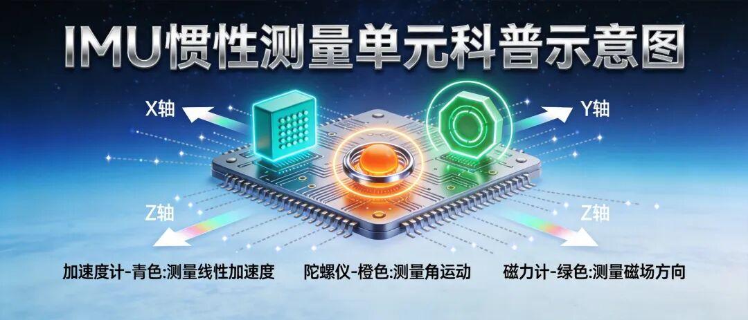
An IMU (Inertial Measurement Unit) consists of two parts:
| Sensor | Measures | Role in Flight Controller |
|---|---|---|
| Accelerometer (Accel) | 3-axis linear acceleration | Static attitude estimation (pitch/roll) |
| Gyroscope (Gyro) | 3-axis angular velocity | Dynamic attitude integration (heading, attitude rate) |
| Magnetometer (Mag, optional) | 3-axis geomagnetic field | Heading correction (prevents gyro drift) |
The IMU determines how fast and how accurately the flight controller “knows where it is.” Position, velocity, attitude—every control algorithm’s input originates here.
But many engineers get dazzled by a string of pretty but useless specs—like “16-bit ADC,” “SPI 10MHz interface,” “operating temperature -40~85°C”…
These are important, but not critical.
The 6 metrics below are what truly determine flight controller performance.
3. The 6 Key Metrics That Truly Determine Flight Controller Performance
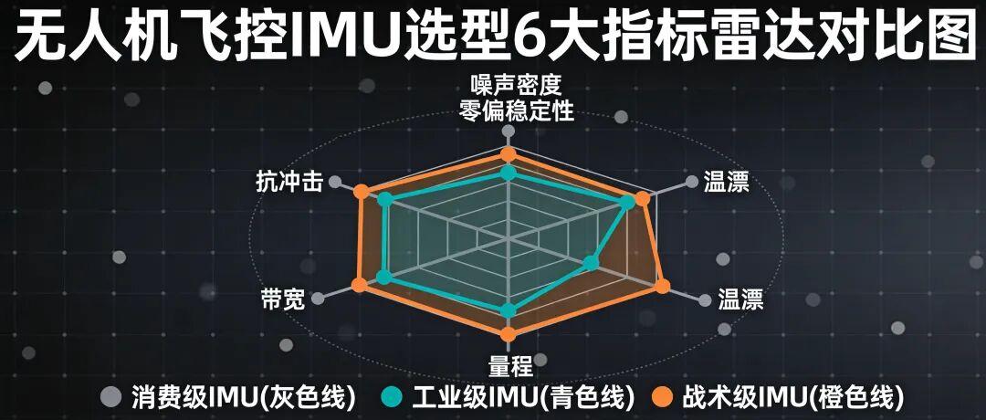
Metric 1: Noise Density—The “Hidden Pit” Most Likely to Trip You Up
Definition: random noise per unit bandwidth, equivalent RMS value at the sensor output.
Units:
- Accelerometer: μg/√Hz
- Gyroscope: °/s/√Hz (or dps/√Hz)
Why it matters:
Noise density directly determines whether the attitude jitters when the flight controller is static. Smaller values mean more stable attitude.
Field experience:
Consumer-grade IMU noise density: typically 200-400 μg/√Hz. Industrial-grade: 30-100 μg/√Hz. Tactical-grade: below 10 μg/√Hz.
Order-of-magnitude differences are clearly visible to the naked eye in flight.
Pitfall:
Many manufacturers only list “noise” without “noise density”. Noise = Noise Density × √(Bandwidth). Always convert to per-unit-bandwidth for comparison, or the data will “look the same” and fool you.
Metric 2: Bias Stability—The “Life-or-Death Line” for Long-Endurance Flights
Definition: the bias drift over time at constant temperature.
Units:
- Gyroscope: °/hr (degrees per hour)
- Accelerometer: μg
Why it matters:
Bias accumulates into angle error over time. A 0.1°/s gyro bias means attitude integration drifts 360° after 1 hour.
Field experience:
Consumer IMU: gyro bias stability typically 10-50 °/hr
Industrial IMU: 1-10 °/hr
Tactical-grade (e.g., ADIS16470 series): <1 °/hr
Pitfalls:
- “Bias” and “bias stability” are two different parameters—manufacturers often conflate them
- Bias can be calibrated; bias stability is a physical chip characteristic that cannot be calibrated away
- For long-endurance/inspection drones, this metric decides whether the job gets done
Metric 3: Temperature Drift—The “#1 Killer” in Industrial Scenarios
Definition: bias shift as temperature changes.
Units: °/s/℃ (gyro); mg/℃ (accelerometer)
Why it matters:
After power-on, the IMU self-heats (100-300mW power draw), typically rising from 25°C room temperature to 50°C. This 25°C swing can cause more bias drift than the initial bias itself.
Field experience:
Industrial scenarios: -20°C ~ +60°C is the baseline
Tactical scenarios: -40°C ~ +85°C to qualify
Some automotive-grade IMUs: -40°C ~ +105°C
Pitfalls:
- Don’t just look at “bias”—demand the “bias vs. temperature” curve
- Temperature compensation is an algorithm concern, but compensation requires the IMU itself to have a small temperature coefficient
- Our opening story—uncontrolled temperature drift taking down 3 prototypes—is the textbook case
Metric 4: Range—Decides Whether It Can “Take the Hit”
Definition: the maximum acceleration/angular velocity the sensor can measure.
Units:
- Accelerometer: g
- Gyroscope: °/s (dps)
Why it matters:
Too small a range means violent maneuvers/crashes saturate the IMU output instantly, and attitude estimation collapses in a moment.
Field experience:
Multirotor normal flight: ±4g accel, ±2000°/s gyro is enough
Agricultural/logistics/inspection high-maneuver scenarios: start at ±8g, ±16g for margin
High-speed/racing drones: ±32g, the more the better
Pitfalls:
- Range and resolution are a trade-off—larger range means lower resolution within range
- Don’t cheap out on small range for industrial use—crashes/impacts make the IMU a consumable part
Metric 5: Bandwidth—The “Ceiling” of High-Speed Response
Definition: the maximum signal frequency the sensor can respond to.
Units: Hz
Why it matters:
The flight controller’s control frequency (typically 1kHz-8kHz) must exceed the IMU’s actual output bandwidth—otherwise high-frequency vibration gets low-pass filtered away and control diverges.
Field experience:
IMU raw bandwidth: 500Hz-1kHz (sufficient)
Actual flight controller use: typically adds a low-pass filter (LPF) down to 50-200Hz
Pitfalls:
- Bandwidth ≠ sampling rate—many beginners confuse them
- Insufficient bandwidth means high-frequency vibration enters the integration stage directly, blowing up angle computation
- Industrial drones should pick IMUs with ≥1kHz bandwidth to leave filtering headroom
Metric 6: Shock Survival—The “Second Life” After a Crash
Definition: the maximum mechanical shock the sensor can survive (without damage + without performance shift).
Units: g (acceleration)
Why it matters:
Crash impacts on the IMU typically reach 100g-500g, far beyond normal operating range. IMUs with poor shock resistance are junk after one crash.
Field experience:
Consumer IMU: 1000g / 0.5ms shock rating
Industrial IMU: 2000g-5000g
Tactical/military-grade: 10000g+
Pitfalls:
- “Shock rating” and “bias change after shock” are two different metrics
- IMUs with large post-shock bias shifts must be recalibrated before flying again
4. Three Real-World Pitfall Cases (With Data)
Cases are anonymized; units simplified.
Case 1: Consumer vs. Industrial—Is 3x the Price Worth It?
| Metric | Consumer IMU-A | Industrial IMU-B |
|---|---|---|
| Price | ¥18 | ¥58 |
| Gyro bias stability | 25 °/hr | 2 °/hr |
| Noise density | 0.03 °/s/√Hz | 0.006 °/s/√Hz |
| Temperature drift | 0.05 °/s/℃ | 0.005 °/s/℃ |
| Static drift (1 hour) | 15° | 0.5° |
Verdict: the consumer IMU is 3x cheaper, but long-endurance flights drift completely off. Used on our inspection drones for 3 months, the failure rate was 4x higher.
Selection iron rule: expensive has its reasons, but match it to the scenario. Toys/trainers use consumer-grade; work/industrial platforms must use industrial-grade.
Case 2: No Temperature Drift Curve in the Datasheet—Found Out After 2,000 Units Produced
A project picked IMU-C to cut costs. The datasheet listed “operating temperature -40~85°C,” but the temperature drift curve column said “refer to data” (i.e., nothing).
After 2,000 units shipped, in northern winter -15°C conditions, gyro bias exceeded spec across the board—attitude estimation diverged, and the aircraft couldn’t even fly a straight line.
Finally swapping IMUs + redoing the temperature compensation algorithm cost ¥800,000 and 6 months.

Selection iron rule: vague datasheet specs hide traps. For core metrics like temperature drift and bias stability, demand measured curves from the manufacturer.
Case 3: Shock Rating Said 1000g—Attitude Never Accurate After a Crash
An FPV project chose an IMU with a 1000g shock rating that looked sufficient. Then one high-speed tree hit: the IMU didn’t break, but the bias permanently shifted 0.5°/s.
Every subsequent power-on required recalibration—useless for field operations.
Selection iron rule: look at “bias change after shock,” not “shock rating.” The former determines the IMU’s “second life.”
5. IMU Selection Checklist (Print It and Stick It on the Wall)
Noise density: accel ≤ 100 μg/√Hz, gyro ≤ 0.01 °/s/√Hz
Bias stability: gyro ≤ 5 °/hr (industrial 1-3 °/hr is excellent)
Temperature drift curve: demand full-range -20°C~+60°C data from the manufacturer
Range: accel ±8g minimum, gyro ±2000°/s
Bandwidth: ≥1kHz
Bias change after shock: smaller is better; industrial ≤ 0.05°/s recommended
Data interface: SPI preferred (better noise immunity than I2C)
Package + soldering: LGA package resists vibration better than QFN
6. Final Words: Choose the Wrong IMU and Everything After Is a “Castle in the Air”
Many junior engineers think: “An IMU just measures acceleration—just pick any cheap one.”
In reality, attitude, position, and velocity estimation in a flight controller gets 70%+ of its accuracy from the IMU. No matter how well you tune the algorithms, a weak IMU means garbage in, garbage out.
Our experience:
1. Don’t blindly trust “domestic replacements”: for core sensors, the gap between industrial and consumer grade is orders of magnitude—use replacements with caution
2. Always verify with measured curves: pretty datasheet data ≠ real parts; validate at least a small batch
3. Long-endurance/work drones use industrial grade: 3x the price for 10x the stability is a great deal
4. Shock survival is your “second life”: a must-check for outdoor operations
Next issue: “Why Does the Power System Need a Watchdog? Drone Power Supply Design Explained”—the “energy center” beside the drone’s “heart.”
If you’re doing flight controller selection, leave a comment telling us your project scenario (inspection/agriculture/logistics/racing…).
If you have any questions about this topic, feel free to contact us at [email protected]
Have questions about this article? Feel free to contact us at [email protected] — we’re happy to help!
Frequently Asked Questions
Q1: What’s the difference between “noise” and “noise density”?
Noise density is noise per unit bandwidth (μg/√Hz for accel, °/s/√Hz for gyro). Total noise = noise density × √(bandwidth). Many datasheets only list total noise, which makes different IMUs look similar—always convert to per-unit-bandwidth to compare fairly. Consumer IMUs run 200-400 μg/√Hz; industrial 30-100 μg/√Hz; tactical below 10 μg/√Hz.
Q2: Why is bias stability critical for long-endurance flights?
Gyro bias integrates into angle error over time—0.1°/s bias means 360° of attitude drift after 1 hour. Bias itself can be calibrated out, but bias stability (drift at constant temperature) is a physical chip characteristic that can’t be calibrated away. Consumer IMUs: 10-50 °/hr; industrial: 1-10 °/hr; tactical (like ADIS16470): <1 °/hr.
Q3: What exactly is temperature drift and why is it the #1 industrial killer?
Temperature drift is bias shift per degree of temperature change (°/s/℃). After power-on, IMUs self-heat from 25°C to ~50°C, and that 25°C swing can cause more drift than the initial bias. Datasheets often hide this—demand the full “bias vs. temperature” curve (-20°C to +60°C minimum) from manufacturers, as one case shows: 2,000 units failed in -15°C winter conditions, costing ¥800,000 and 6 months.
Q4: What IMU range and bandwidth should industrial drones use?
Range: ±8g accelerometer minimum (±16g for margin), ±2000°/s gyro—crashes hit 100-500g and saturate small-range IMUs, collapsing attitude estimation. Bandwidth: ≥1kHz so the control loop (1kHz-8kHz) isn’t starved; flight controllers typically add an LPF down to 50-200Hz. Remember bandwidth ≠ sampling rate.
Q5: What does “shock survival” really mean for IMU selection?
Two separate metrics: shock rating (max g the chip survives, e.g., consumer 1000g/0.5ms, industrial 2000-5000g, tactical 10000g+) and bias change after shock. A chip that survives but shifts bias 0.5°/s permanently after a crash must be recalibrated before every flight—effectively dead for field use. Always check post-shock bias change (≤0.05°/s recommended for industrial).
