
Key Takeaways
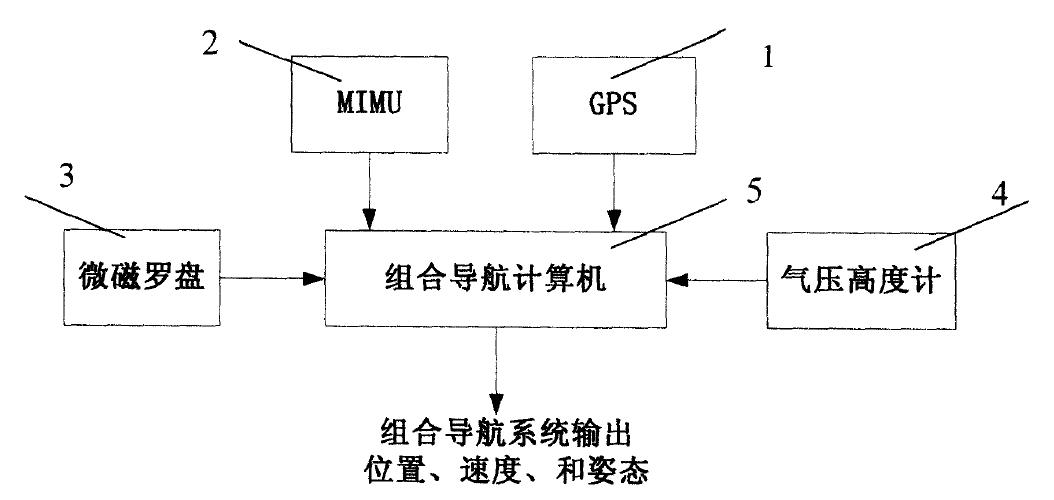
- A single integrated hardware unit combines a MEMS IMU, a GPS receiver, a micro magnetic compass and a barometric altimeter, feeding one navigation computer that outputs position, velocity and attitude.
- Three embedded processors split the workload: GPS/compass/altitude solving plus the fusion filter, high-speed IMU acquisition, and strapdown inertial solving.
- A multi-rate Kalman filter fuses inertial data at 50–100 Hz with GPS fixes at 1–5 Hz, and estimates gyro and accelerometer constant drift online so it can be fed back into calibration.
- Fault diagnosis degrades gracefully: losing the compass, the barometer, GPS, or any pair of them reconfigures the filter instead of stopping output. Only an IMU failure halts the system.
For small UAVs no single sensor is good enough on its own. A MEMS IMU is small, cheap and wide-band, but its errors grow without bound. GPS is accurate horizontally yet tens of meters off vertically, and it cannot observe heading at all. A magnetic compass supplies non-diverging heading, and a barometer supplies relative altitude down to meter or decimeter level. This patent filing — “A Highly Integrated MIMU/GPS/Micro Magnetic Compass/Barometric Altimeter Integrated Navigation System” — puts all four into one box and lets a Kalman filter use each sensor to cover the weaknesses of the others. Aomway walks through the architecture, the data flow and the fault-tolerance logic below.
Why Combine These Four Sensors
The design starts from a simple observation about complementary error behaviour. Each sensor fails in a different dimension and on a different time scale, so the blind spot of one is exactly where another is strongest.
| Subsystem | What it measures | Strength | Limitation |
|---|---|---|---|
| MIMU (MEMS IMU) | Angular rate and linear acceleration | Small, low cost, wide dynamic range, high output rate (50–100 Hz) | Position and attitude errors accumulate with time; unusable alone for long missions |
| GPS | Position and velocity | Meter-level horizontal accuracy, no error accumulation | Vertical error of ten to several tens of meters; provides no heading |
| Micro magnetic compass | Three-axis magnetic field plus two-axis acceleration | Absolute heading that does not diverge | Needs disturbance rejection and calibration; sensitive to magnetic interference |
| Barometric altimeter | Atmospheric pressure, converted to relative altitude | Meter to decimeter relative altitude during motion | Needs an initial altitude reference to produce absolute height |
Because the four error signatures are close to orthogonal — inertial error grows with time, GPS error is bounded but biased in altitude and blind to heading, compass heading is bounded but noisy, barometric altitude is bounded but drifts with weather — one filter can bound all of them at once.
System Architecture: Four Subsystems, One Computer
The system is split into five parts: the MIMU subsystem, the GPS subsystem, the micro magnetic compass subsystem, the barometric altimeter subsystem and the integrated navigation computer. The computer handles every subsystem’s data, performs the fusion, and finally outputs the vehicle’s position, velocity and attitude.
Physically, the four navigation subsystems share one highly integrated hardware assembly, and the computer is built on three embedded microprocessors. The design also reuses processing capacity: GPS, the micro magnetic compass and the barometric altimeter all share a single microprocessor, which saves the three separate processor resources they would otherwise each require.
MIMU Subsystem
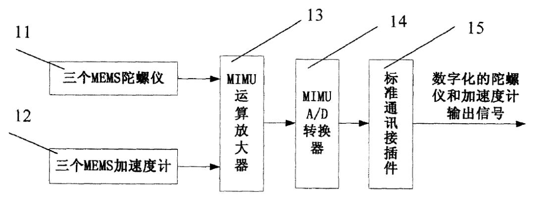
The MIMU subsystem contains three MEMS gyroscopes, three MEMS accelerometers, an MIMU operational amplifier, an MIMU A/D converter and a standard communications connector. The gyroscopes and accelerometers output angular rate and linear acceleration as analog signals; after amplification and A/D conversion these become digital and leave through the standard connector to microprocessor II.
GPS Subsystem
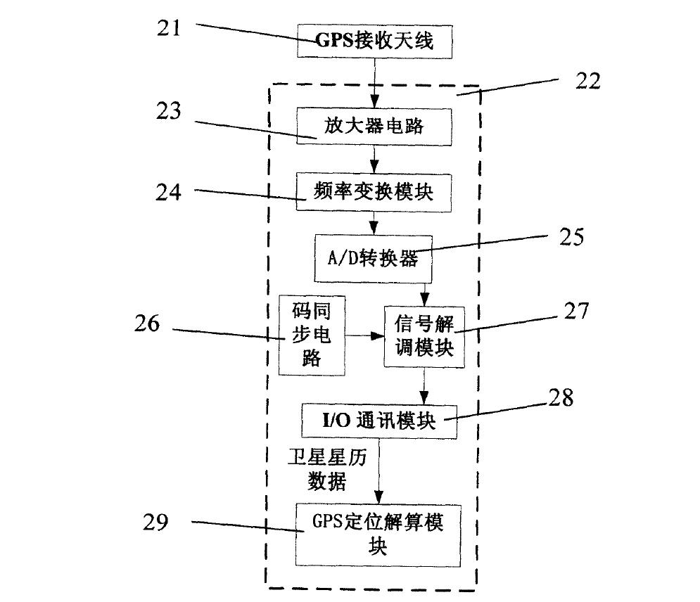
The GPS subsystem is built from a receiving antenna and an embedded GPS receiver. The receiver comprises an amplifier circuit, a frequency conversion module, an A/D converter, a code synchronization circuit, a signal demodulation module, an I/O communications module and a GPS positioning algorithm module.
The antenna picks up the satellite RF signal. After amplification and frequency conversion it becomes an intermediate-frequency signal; A/D conversion, code synchronization and demodulation then yield the GPS navigation data. That data passes through the I/O module to microprocessor I, which solves vehicle position and velocity in the positioning algorithm module.
Micro Magnetic Compass Subsystem
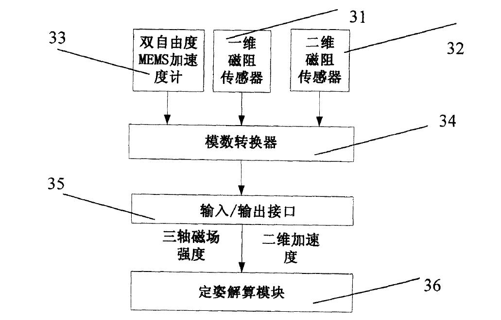
The compass uses a one-axis magnetoresistive sensor, a two-axis magnetoresistive sensor, a two-degree-of-freedom MEMS accelerometer, an A/D converter, an input/output interface and an attitude algorithm module. The magnetoresistive sensors measure three-axis magnetic field strength; the two-axis accelerometer measures acceleration along the east and north directions. The analog signals are digitized and handed to microprocessor I, where the attitude module solves the vehicle’s three-dimensional attitude.
Barometric Altimeter Subsystem
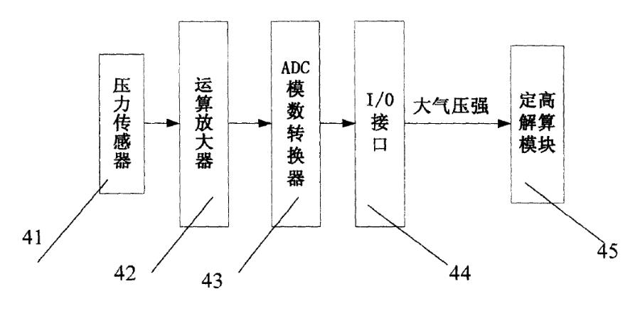
The altimeter consists of a pressure sensor, an operational amplifier, an ADC, an I/O interface and an altitude algorithm module. The pressure sensor measures the ambient pressure corresponding to altitude; after amplification and digitization the value goes to microprocessor I, and the altitude module converts it into vehicle height.
The Three-Processor Navigation Computer
The navigation computer uses three embedded high-performance processors — the filing names the AT91RM9200, ADSP2106X and ADSP2136X families — with a clear division of labour.
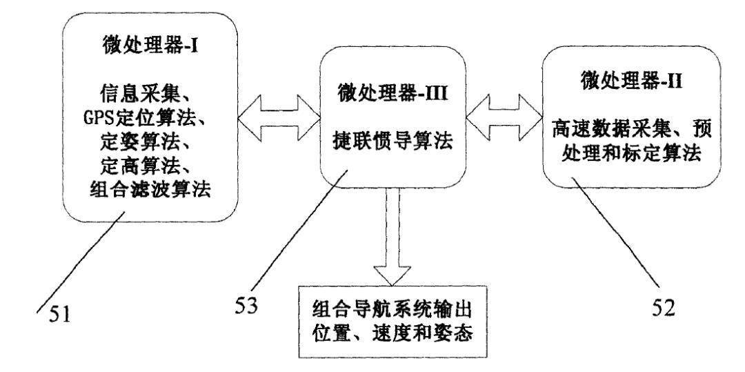
Microprocessor I runs the algorithm stack: GPS positioning, compass attitude solving, barometric altitude solving, and the multi-rate multi-model Kalman filter that fuses all four sources. When the filter completes, it hands the result to microprocessor III for correction.
Microprocessor II handles high-speed MIMU acquisition. It samples raw gyro and accelerometer data, applies smoothing and low-pass pre-filtering, performs system error calibration and compensation, then passes the result to microprocessor III.
Microprocessor III runs the strapdown inertial solution. It sends the resulting motion parameters back to microprocessor I for the fusion filter, and on the other channel it streams position, velocity and attitude to the user continuously in real time.
Navigation Data Flow: Four Branches, One Filter
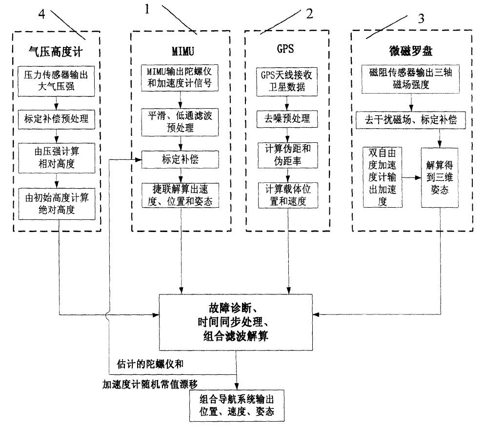
Navigation solving splits into four data-processing branches and one combined filter.
- MIMU branch. High-rate angular rate and acceleration leave the IMU, pass smoothing and low-pass pre-filtering, then calibration compensation, and finally the strapdown algorithm to produce velocity, position and attitude.
- GPS branch. Demodulated GPS navigation data is de-noised, satellite pseudorange and pseudorange rate are computed, and the positioning algorithm solves vehicle velocity and position.
- Compass branch. Three-axis magnetic field strength and east/north acceleration come out of the sensors; the magnetic field is cleaned of disturbance and calibrated, then combined with the acceleration in the attitude algorithm to solve 3D attitude.
- Barometer branch. Atmospheric pressure is calibrated and compensated, converted to relative altitude by the pressure-to-height algorithm, and combined with the initial altitude to give absolute altitude.
The branches run at very different rates: the MIMU strapdown algorithm is fastest at roughly 50–100 Hz, while GPS positioning is slowest at roughly 1–5 Hz. That spread is exactly what the multi-rate processing design has to absorb.
After fault diagnosis and time synchronization, the four streams enter the combined filter. The filter estimates vehicle position, velocity and attitude on one hand, and the constant random drift of the gyroscopes and accelerometers on the other. Position, velocity and attitude become the system output; the estimated drift is fed back into the calibration and compensation stage, which corrects device error and raises accuracy — including the accuracy of the standalone strapdown solution.
Fault Diagnosis and Time Synchronization
The fault strategy is deliberately asymmetric. If the MIMU subsystem fails, the system stops outputting — inertial data is the backbone and there is nothing to fall back on. If GPS, the compass or the barometer fails, whether one of them, any two, or all three, the system degrades into a combined navigation system built only from the healthy subsystems. A failed barometer, for instance, leaves a MIMU/GPS/compass system.
Time synchronization matters just as much. The combined filter requires that fused information be consistent in time, so every navigation subsystem tags its data with a timestamp. The system compares timestamps and fuses only information that lines up. Fusion itself uses a basic Kalman filter.
Technical Advantages
Bringing the four navigation methods together yields four concrete benefits.
- Higher accuracy, bounded divergence. The filter delivers position, velocity and attitude that are both accurate and non-diverging, and estimates gyro and accelerometer constant random drift online. Once corrected, even the pure strapdown inertial solution improves.
- Fault tolerance and reliability. Fusing four navigation systems raises the system’s ability to keep working through sensor failures.
- Lower cost and mass. MEMS gyroscopes and accelerometers cut system cost and weight while widening dynamic range and improving response speed.
- Better use of computing resources. Three embedded microprocessors handle several complex tasks at once with redundancy and reuse — one processor doubles as the algorithm engine for GPS, the compass and the barometer, and as the fusion filter engine.
Taken together, the system is small, inexpensive, reliable, fast-responding and accurate — which is why the filing targets precision navigation for micro and small aerial vehicles.
Have questions about this article? Feel free to contact us at [email protected] — we’re happy to help!
Frequently Asked Questions
What is a MIMU, and why use one instead of a tactical-grade IMU?
A MIMU is a miniature inertial measurement unit built from MEMS gyroscopes and accelerometers. It is small, cheap, light and has a wide dynamic range, but its position and attitude errors accumulate over time. That is why this design pairs it with GPS, a compass and a barometer instead of relying on it alone.
Why can’t GPS supply altitude and heading by itself?
GPS gives meter-level horizontal accuracy with no error accumulation, but its vertical accuracy is only in the range of ten to several tens of meters, and it cannot observe heading at all. The design therefore takes altitude from a barometric altimeter and heading from a magnetic compass, using GPS mainly for horizontal position and velocity.
What happens when one sensor fails mid-flight?
The system degrades instead of shutting down. If GPS, the compass or the barometer fails, whether one, two or all three, the filter reconfigures to use only the healthy subsystems, so a dead barometer leaves a MIMU/GPS/compass system. Only a MIMU failure stops output entirely, because the inertial solution is the backbone.
Why does the design need three microprocessors?
The workload is naturally parallel. One processor runs GPS, compass, altitude and fusion algorithms; a second handles high-speed IMU sampling, filtering and calibration; a third runs the strapdown inertial solution and streams output. Splitting them keeps the 50–100 Hz inertial loop from being blocked by slower navigation tasks.
Why is time synchronization critical in multi-sensor fusion?
A Kalman filter can only fuse measurements that describe the same instant. The branches run from 1–5 Hz up to 50–100 Hz, so every subsystem timestamps its data and the system fuses only time-aligned information. Without that step, a fresh inertial sample could be blended with a stale GPS fix and inject error.
Source: 雨飞工作室, “一种高集成度MIMU/GPS/微磁罗盘/气压高度计组合导航系统” (WeChat). Original article: mp.weixin.qq.com.
About Aomway
Aomway designs and manufactures FPV video transmitters, antennas, cameras and goggle systems for drone pilots worldwide, with more than fifteen years in the UAV industry. Its hardware is used across racing, long-range and professional aerial platforms.