Editor’s note
CRSF is not a simple “RC channel format” like SBUS. It is a high-speed bidirectional communication protocol running over UART. It can deliver RC channel data from the transmitter to the flight controller, while simultaneously transmitting battery, current, GPS, flight mode, and link quality information back to the transmitter. CRSF also supports device discovery, parameter read/write, and Lua script menu interaction.
1. CRSF Protocol Overview and Interface
CRSF (Crossfire Serial Protocol) originated from the TBS Crossfire system. ExpressLRS and other RC links also widely use CRSF as the interface protocol between receiver and flight controller.
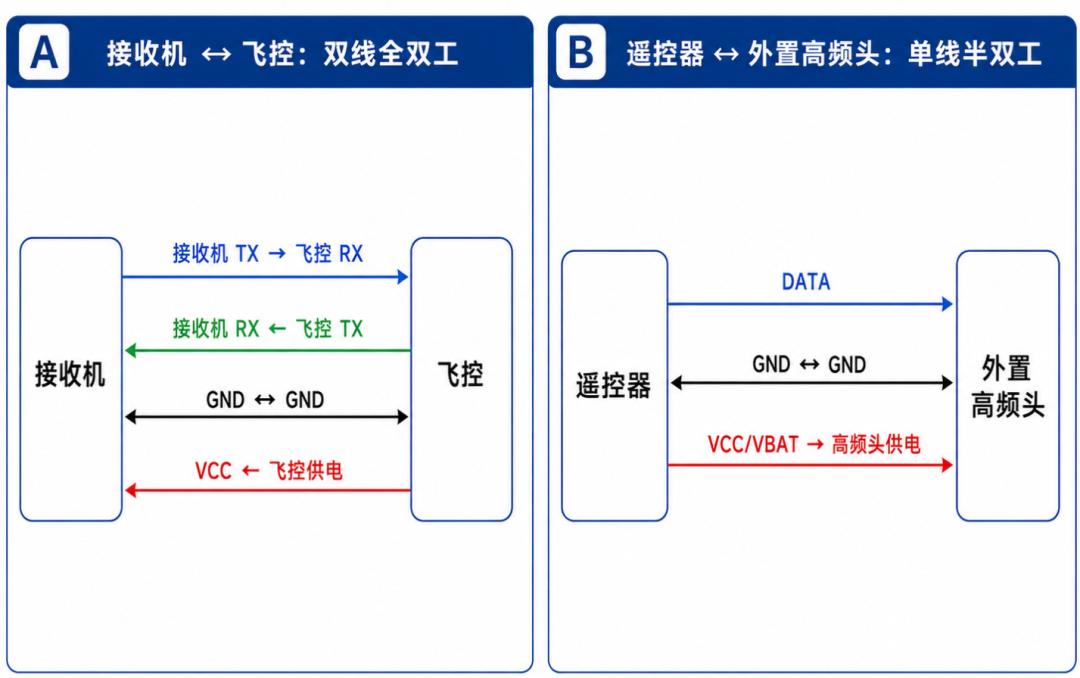
Figure 1: CRSF two-wire full-duplex and single-wire half-duplex connection diagrams
In practice, CRSF appears in two locations:
- Transmitter MCU ↔ External RF module
- Receiver ↔ Flight controller
Both locations can use CRSF, but the hardware connection differs.
A. Receiver to Flight Controller: Two-Wire Full-Duplex
The most common CRSF wiring on the flight controller side is standard UART dual-wire:
- Receiver TX → Flight Controller RX
- Receiver RX ← Flight Controller TX
- GND ↔ Flight Controller GND
- Receiver VCC ← Flight Controller power
In this configuration, the receiver continuously sends RC channel frames to the flight controller while the flight controller simultaneously transmits telemetry data back.
| Parameter | Common Value |
|---|---|
| Communication | UART |
| Baud rate | 416666 bps |
| Data format | 8N1 |
| Logic level | 3.0V ~ 3.3V |
| Signal logic | Non-inverted |
| Direction | Two-wire full-duplex |
Full-duplex is simpler and more stable — no bus contention, no GPIO direction switching.
The 416666 bps rate may seem unusual, but it is the standard CRSF high-speed UART rate on the flight controller side. Unlike conventional PC serial rates (9600, 115200), it is designed for low-latency RC link communication.
At 416666 bps, each bit takes ~2.4µs. With UART 8N1, each byte requires ~10 bits on the wire, so byte transmission time is ~24µs. A 26-byte RC channel frame takes approximately 0.62ms to transmit. This is one reason CRSF can simultaneously handle RC channels, link status, and telemetry at low latency.
B. Transmitter to RF Module: Single-Wire Half-Duplex
CRSF also supports single-wire half-duplex mode, common between the transmitter MCU and external RF module. A single DATA line handles both transmission and reception. The key constraint: only one side may transmit at a time; the other must be in receive or high-impedance state.
Single-wire half-duplex CRSF relies on master-slave timing and direction switching rather than complex arbitration. The transmitter acts as timing controller; the RF module responds.
Three key software actions:
- Switch DATA pin to output / UART TX before sending
- Transmit CRSF frame normally
- After transmission, disable output driver, release the bus, switch back to input / UART RX
Releasing the bus is critical. If the driver continues to push output after sending, it blocks the response and causes bus contention.
For flight controller-receiver interfaces, full-duplex is strongly preferred. Aomway’s engineering team always uses two-wire full-duplex for FC-receiver CRSF connections in our drone platforms — it eliminates an entire class of timing bugs.
2. CRSF Frame Structure and Common Type Values
CRSF uses variable-length frames, not fixed-length frames.
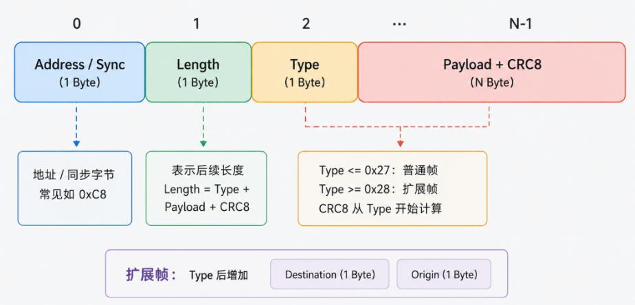
Figure 2: CRSF data frame structure
| Field | Description |
|---|---|
| Address | Address or sync byte |
| Length | Subsequent data length |
| Type | Frame type |
| Payload | Data content |
| CRC8 | Checksum byte |
2.1 Does CRSF Have a Fixed Header?
Unlike SBUS (which always starts with 0x0F), CRSF has no invariant frame header. The first byte (Address/Sync) serves as both address and frame-start synchronizer.
For RC channel frames from receiver to flight controller, the first byte is typically 0xC8 (Flight Controller address). However, payload bytes could also happen to contain 0xC8, so relying on Address alone is insufficient for synchronization.
Proper parsing: search for candidate Address/Sync byte → read Length → validate plausibility → verify with CRC8. CRSF synchronization relies on Address + Length + Type + CRC8 jointly, not on any single fixed header.
2.2 Length Semantics
Length does not include Address or Length itself. It represents: Length = Type + Payload + CRC8 total bytes.
For example, Length = 0x18 (decimal 24) means Type (1 byte) + Payload (22 bytes) + CRC8 (1 byte) = 24 bytes.
CRSF single frames generally do not exceed 64 bytes. If Length exceeds a reasonable range during parsing, discard and resynchronize.
2.3 Type Determines Frame Structure
Type ≤ 0x27: Standard frame
Type ≥ 0x28: Extended frame
This division is inherent to CRSF’s Frame Type address space:
- 0x00–0x27: Standard frame type region
- 0x28–0xFF: Extended frame type region
When Type ≥ 0x28, two additional bytes follow Type: Destination Address and Origin Address, specifying the recipient and sender.
2.4 Common Address Values
| Address | Meaning |
|---|---|
| 0x00 | Broadcast |
| 0xC8 | Flight Controller |
| 0xEA | Remote Control |
| 0xEC | R/C Receiver |
| 0xEE | R/C Transmitter Module |
2.5 CRC8 Checksum
CRSF frames end with a CRC8 checksum using polynomial 0xD5. CRC calculation covers Type through the last Payload byte — excluding Address, Length, and CRC itself. For extended frames, Destination and Origin are included in the CRC calculation.
2.6 Common Type Values
| Type | Name | Purpose | Category |
|---|---|---|---|
| 0x02 | GPS | GPS telemetry | Standard |
| 0x08 | Battery Sensor | Voltage, current, capacity | Standard |
| 0x14 | Link Statistics | Link quality, RSSI, SNR, TX power | Standard |
| 0x16 | RC Channels Packed | 16-channel RC data | Standard |
| 0x1C | Link Statistics RX | Receiver-side link stats | Standard |
| 0x1D | Link Statistics TX | Transmitter-side link stats | Standard |
| 0x1E | Attitude | Attitude data | Standard |
| 0x21 | Flight Mode | Current FC mode string | Standard |
| 0x28 | Parameter Ping Devices | Device discovery | Extended |
| 0x29 | Parameter Device Information | Device parameter info | Extended |
| 0x2B | Parameter Settings Entry | Parameter definition | Extended |
| 0x2C | Parameter Settings Read | Read parameter | Extended |
| 0x2D | Parameter Value Write | Write parameter | Extended |
| 0x32 | Direct Commands | Direct device commands | Extended |
| 0x7A | MSP Request | MSP request passthrough | Extended |
| 0x7B | MSP Response | MSP response passthrough | Extended |
| 0xAA | CRSF MAVLink Envelope | MAVLink encapsulation | Extended |
3. Typical Frame Examples
Having covered the basic structure and common types, let’s connect the dots with two typical scenarios: the RC channel frame (most used by flight controllers) and the extended frame for Lua parameter interaction.
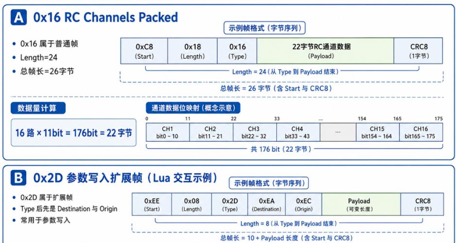
Figure 3: 0x16 RC channel frame and 0x2D Lua parameter extended frame examples
3.1 0x16 RC Channels Packed Frame
For RC input, the core frame is 0x16 RC Channels Packed. Since 0x16 ≤ 0x27, it is a standard frame — Type is followed directly by the RC channel payload.
Typical format: 0xC8 0x18 0x16 [22-byte RC channel data] CRC8
Length = 0x18 (24) = Type (1) + Payload (22) + CRC8 (1).
CRSF RC channel data is not 2 bytes per channel. Instead, 16 channels × 11 bits = 176 bits, packed into 22 bytes × 8 bits = 176 bits. Unpacking extracts 16 channels of 11-bit values sequentially. Packing reverses the process.
CRSF RC channel values are not PWM pulse widths. Typical mapping: 192 ≈ 1000µs, 992 ≈ 1500µs, 1792 ≈ 2000µs. Aomway’s flight controller implementations use this mapping for consistent RC input across different receiver types.
3.2 Lua Parameter Interaction Extended Frame
Extended frames are used for device discovery, parameter read/write, and Lua script menu interaction. When you open the ELRS or Crossfire Lua configuration interface on an EdgeTX/OpenTX transmitter, the controller reads parameter lists from the module or receiver and writes modified values back — all via CRSF extended frames.
Extended frame example: EE 08 2D EA EC [Payload…] CRC
| Field | Value / Meaning |
|---|---|
| Address | 0xEE (Transmitter Module) |
| Length | 0x08 |
| Type | 0x2D (Parameter Value Write) |
| Destination | 0xEA (Remote Control) |
| Origin | 0xEC (R/C Receiver) |
| Payload | Subsequent data |
| CRC8 | Last byte |
0x2D is for parameter writes; parameter reads and entry returns use 0x2C and 0x2B respectively. Lua menu interaction typically uses these parameter-related extended frames for device parameter read/write operations.
4. Failsafe
CRSF failsafe cannot rely on a single fixed flag bit. It requires comprehensive judgment: whether 0x16 RC channel frames are being received continuously, CRC correctness, RC frame interval timeout, and link statistics frame anomalies.
- 0x16 received with valid CRC: RC input is valid
- 0x16 not received for a short period: possible packet loss
- 0x16 not received for an extended period: enter RC failsafe
Because CRSF includes CRC8, the receiver can distinguish between: received error frame, no frame received, and received valid frame. This is a significant advantage over protocols without checksums, and Aomway leverages this in our failsafe detection logic for industrial drone platforms.
5. Summary
CRSF is a UART-based high-speed bidirectional RC and telemetry protocol with variable-length frames. It uses Address/Length/Type/Payload/CRC8 structure, commonly at 416666 bps 8N1, non-inverted, on the flight controller side.
Key takeaways:
- CRSF uses variable-length frames
- No fixed frame header — synchronization relies on Address + Length + CRC jointly
- Length excludes Address and Length itself
- CRC8 is calculated from Type through the last Payload byte
- 0x16 frame carries 16 channels of 11-bit RC data
- Type ≥ 0x28 triggers extended frame handling
Have questions about CRSF protocol implementation, receiver configuration, or flight controller integration? Contact Aomway at [email protected] — our team provides protocol-level consulting and system integration support for drone platforms.
Frequently Asked Questions
1. What is the difference between CRSF and SBUS protocols?
SBUS is a one-way protocol that only transmits RC channel data from receiver to flight controller at a fixed 100kbps. CRSF is bidirectional, running at 416666 bps, supporting simultaneous RC channel transmission and telemetry back to the transmitter. CRSF also supports device discovery, parameter read/write, and Lua script interaction via extended frames — none of which SBUS offers. Aomway recommends CRSF for any modern drone platform requiring real-time telemetry or in-flight parameter adjustment.
2. Why does CRSF use 416666 bps instead of standard baud rates?
416666 bps is optimized for low-latency RC communication. At this rate, a 26-byte RC channel frame completes transmission in ~0.62ms, enabling the high update rates needed for responsive flight control. Standard baud rates like 115200 would introduce unacceptable latency for RC control loops running at 1-8kHz. The non-standard rate is a deliberate design choice shared across TBS Crossfire and ExpressLRS ecosystems.
3. How does CRSF handle frame synchronization without a fixed header byte?
CRSF achieves synchronization through a combination of Address/Sync byte validation, Length range checking, and CRC8 verification. The parser searches for candidate sync bytes, reads the Length field, validates it falls within acceptable range (≤64 bytes), and confirms the entire frame with CRC8. This multi-layered approach is more robust than relying on a single fixed header, as it prevents false synchronization from payload bytes that coincidentally match the sync value.
4. Can I use CRSF with I2C instead of UART?
No. CRSF is designed exclusively for UART communication. I2C’s addressing scheme and slower clock speeds (typically 400kHz) are incompatible with CRSF’s 416666 bps requirement and frame structure. For flight controller integration, always use a dedicated UART port configured for CRSF protocol. SPI is used internally by some receiver modules but is not part of the CRSF specification for external interfaces.
5. How do I implement CRSF failsafe detection in my flight controller?
Implement a multi-condition failsafe detector: (1) Track time since last valid 0x16 frame with correct CRC8; (2) Monitor link statistics frames (0x14) for RSSI/SNR degradation; (3) Define a short-term timeout (e.g., 100ms) for packet loss warning and a long-term timeout (e.g., 1s) for full failsafe. Log all failsafe events for post-flight analysis. Aomway’s industrial drone platforms use a 3-tier failsafe system: warning, hold-position, and autonomous landing, triggered by progressively longer signal loss durations.
Building a drone system and need help with CRSF integration? Contact Aomway at [email protected] — we provide protocol implementation, receiver configuration, and flight controller development services for industrial UAV applications.
