Editor’s note
SBUS may look like ordinary serial, but it has several gotchas: it typically uses 100000 8E2, standard signals are often inverted logic; each frame is fixed at 25 bytes, with 16 proportional channels packed as 11-bit continuous data; the protocol itself has no CRC or checksum — do not confuse UART even parity with SBUS frame-level validation.
1. SBUS Protocol Overview
SBUS is a common digital RC protocol used between RC receivers and flight controllers, robot controllers, or other downstream devices to transmit RC channel data.
Traditional PWM signals use one wire per channel, while SBUS transmits multiple channels over a single signal line. This simplifies wiring, supports more channels, and is better suited for multi-channel flight control systems.
At its core, SBUS is: a UART-based, fixed-length multi-channel RC data frame protocol.
It is not PWM, not PPM — it is a digital serial protocol.
2. SBUS Communication Parameters
| Parameter | Value |
|---|---|
| Communication | UART asynchronous serial |
| Baud rate | 100000 bps |
| Data format | 8E2 |
| Parity | Even |
| Stop bits | 2 |
| Signal logic | Typically inverted |
| Frame length | 25 bytes |
| Proportional channels | 16 |
| Digital channels | 2 |
| Channel bit width | 11 bits |
| Channel raw range | 0 ~ 2047 |
Most ordinary serial ports default to 115200 8N1, while standard SBUS uses 100000 8E2, and most SBUS signals use inverted logic.
3. SBUS Frame Structure
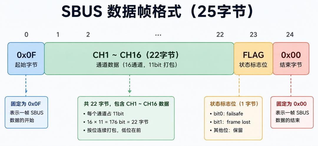
A standard SBUS frame is fixed at 25 bytes:
| Byte Position | Content |
|---|---|
| Byte 0 | Header, 0x0F |
| Byte 1–22 | 16 proportional channel data |
| Byte 23 | Status flags |
| Byte 24 | Footer, typically 0x00 |
Byte 0      : 0x0F
Byte 1–22   : 16 proportional channels, 11-bit packed
Byte 23     : Status flags
Byte 24     : Footer, typically 0x00
4. SBUS Has No Protocol-Level Checksum
SBUS has no CRC, checksum, or any protocol-level integrity check field. Unlike CRSF and other modern protocols, the 25-byte SBUS frame contains no frame-level validation.
The 8E2 format includes even parity, but this is a UART hardware-level per-byte parity check — it is NOT an SBUS protocol-level integrity check for the entire 25-byte frame. This distinction is critical: a corrupted frame can pass UART parity checks if individual bytes happen to maintain even parity.
Aomway’s flight controller implementations add application-level validation: checking the 0x0F header byte, verifying the footer, and monitoring frame timing to detect corrupted SBUS frames despite the protocol’s lack of built-in checksum.
5. SBUS Channel Data Format
Each SBUS frame contains 16 proportional channels, each represented as 11 bits. The raw range per channel is:
0 ~ 2047Because channel data is tightly packed, it is not aligned to 8-bit, 16-bit, or 32-bit boundaries. A single channel’s data may span two or even three bytes.
Byte 1–22 = 176 bits total

CH1  : bit 0   ~ bit 10
CH2  : bit 11  ~ bit 21
CH3  : bit 22  ~ bit 32
CH4  : bit 33  ~ bit 43
...
CH16 : bit 165 ~ bit 175
6. SBUS Status Flags (Byte 23)
| Bit | Meaning |
|---|---|
| bit 0 | Channel 17 (digital) |
| bit 1 | Channel 18 (digital) |
| bit 2 | Frame Lost |
| bit 3 | Failsafe |
| bit 4–7 | Reserved |
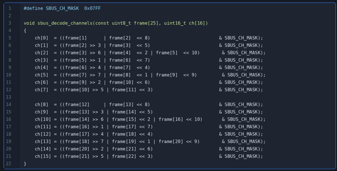
7. Receiver-Side Channel Unpacking Code
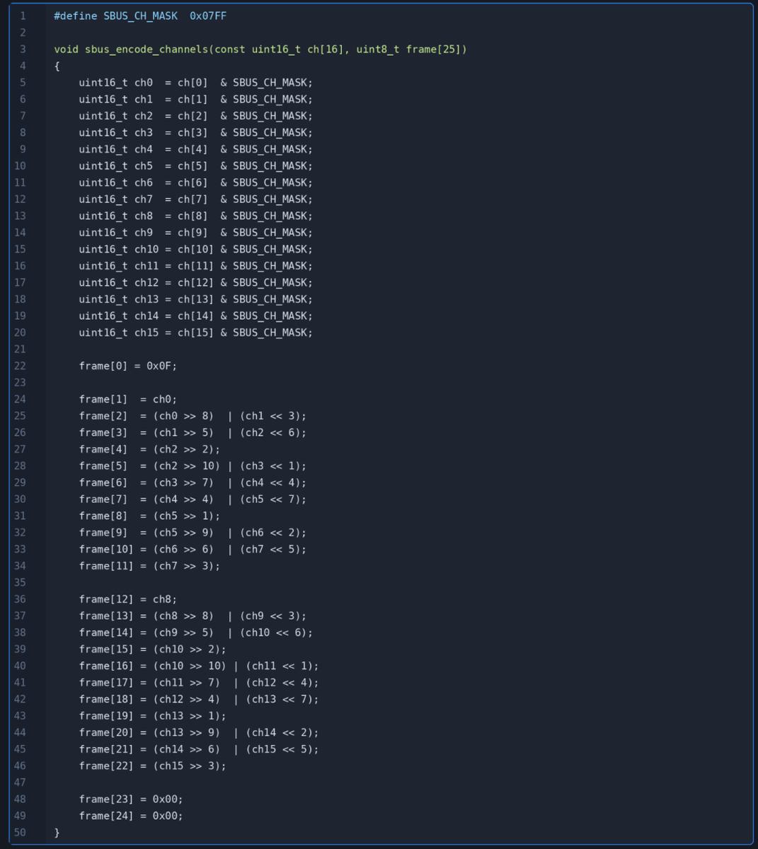
8. Transmitter-Side Channel Packing Code
9. SBUS Signal Inversion Circuit
Standard SBUS signals typically use inverted logic. Ordinary UART idle state is high, while standard SBUS output logic is the opposite.
Therefore, receiving standard SBUS usually requires signal inversion. Three common approaches: MCU UART RX hardware inversion, NPN transistor inverter, and logic gate inverter.
NPN transistor inverter circuit:
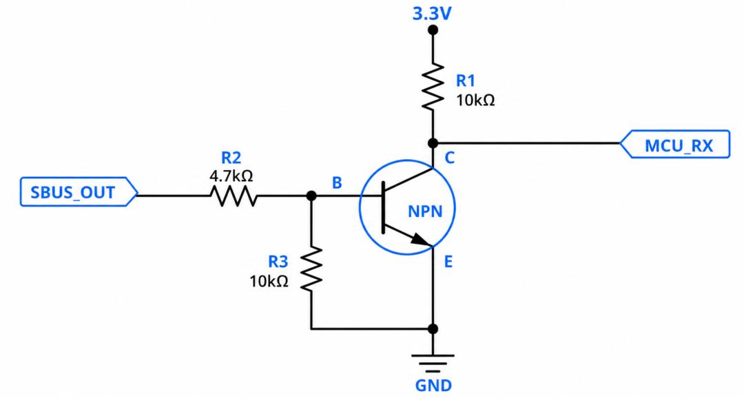
Operation:
- When SBUS_OUT is high, NPN conducts, pulling MCU_RX low
- When SBUS_OUT is low, NPN cutoff, MCU_RX pulled high by Rc
- This completes one logic inversion cycle
Notes:
- MCU_RX pull-up voltage should match MCU IO voltage (e.g., 3.3V)
- Receiver and MCU must share common ground
- If the receiver outputs non-inverted SBUS, or the MCU has UART RX inversion enabled, do NOT add an additional inverter circuit
Logic gate inverter option: Use devices like 74LVC1G04. For poor signal edges, long cables, or better noise immunity, consider inverters with Schmitt trigger inputs. Aomway’s drone receiver designs use Schmitt-trigger inverters for reliable SBUS signal conditioning in electrically noisy environments.
10. Most Common Implementation Mistakes
| Problem | Description |
|---|---|
| Wrong serial parameters | Standard SBUS uses 100000 8E2, not 115200 8N1 |
| Missing signal inversion | Standard SBUS typically requires inversion before feeding to ordinary UART |
| Assuming CRC exists | SBUS has no protocol-level CRC/Checksum |
| Channel bit shift errors | 16 channels are 11-bit packed, not 16-bit aligned |
11. Summary
Fixed 25-byte frame
Byte 0     : Header 0x0F
Byte 1–22  : 16 channels, 11-bit packed
Byte 23    : Status flags
Byte 24    : Footer, typically 0x00
No protocol-level CRC/Checksum
Standard serial: 100000 8E2
Standard signal: inverted logic
Three core concepts to remember:
- 16 channels are packed as continuous 11-bit values
- SBUS has no frame-level checksum
- Standard SBUS typically requires inversion before connecting to ordinary UART
Have questions about SBUS implementation, signal conditioning, or receiver integration? Contact Aomway at [email protected] — our engineering team provides protocol consulting and hardware design services for drone platforms.
Frequently Asked Questions
1. Why does SBUS use 100000 bps instead of standard baud rates like 115200?
SBUS was designed by Futaba for low-latency RC control. The 100000 bps rate, combined with the 25-byte fixed frame, ensures fresh RC data arrives approximately every 14ms (7ms in high-speed mode). Standard baud rates don’t divide evenly into the SBUS frame timing requirements. This non-standard rate is one reason why not all UART hardware supports SBUS — the controller must be able to generate the exact 100000 bps clock.
2. How do I know if my SBUS signal is inverted or non-inverted?
If you connect SBUS directly to a standard UART and receive only garbage data (or all zeros), the signal is likely inverted. You can verify by checking the idle voltage level: standard SBUS idles low (inverted), while normal UART idles high. Some modern receivers (e.g., certain ExpressLRS receivers) can output non-inverted SBUS via configuration. Check your receiver documentation. Aomway recommends testing with an oscilloscope if available — the idle level immediately reveals whether inversion is needed.
3. How do I validate SBUS frame integrity without a CRC?
Without protocol-level checksums, validate by checking: (1) Header byte equals 0x0F; (2) Footer byte equals 0x00 (or is within expected range); (3) Frame timing is consistent (frames arrive at expected intervals); (4) Channel values are within reasonable ranges (e.g., 100-1900 for normal RC positions). For critical applications, implement a rolling average filter to detect and reject sudden anomalous frame values. Aomway’s flight controllers use multi-frame validation before committing to failsafe transitions.
4. What is the difference between SBUS and SBUS2?
SBUS (original) is the standard 25-byte protocol described in this article. SBUS2 is Futaba’s extension that adds telemetry data by appending additional bytes after the standard 25-byte frame. SBUS2 includes sensor data (voltage, temperature, RPM, etc.) from Futaba telemetry sensors. However, SBUS2 is proprietary to Futaba and not as widely adopted. ExpressLRS and most modern systems use CRSF instead, which offers bidirectional communication and proper checksums.
5. Can I use SBUS and CRSF simultaneously on the same flight controller?
Typically no — each protocol requires a dedicated UART port configured for that specific protocol. However, some flight controller firmware (like Betaflight and INAV) support protocol auto-detection on certain UART ports. You cannot mix SBUS and CRSF on the same physical UART simultaneously. If you need multiple receiver types for redundancy, use separate UART ports. Aomway’s dual-receiver drone platforms use two independent UARTs — one for SBUS and one for CRSF — with the flight controller handling receiver switching logic.
Need help with SBUS or CRSF integration in your drone system? Contact Aomway at [email protected] — we provide protocol implementation, hardware design, and flight controller consulting for industrial UAV applications.
