

Industrial Flight Control · Article 22
Opening: Drifting on Takeoff? Don’t Reach for the PID Manual Yet
A reader recently wrote in:
“My aircraft powers on and arms normally, but the moment I push throttle the nose yaws left. Switching to Loiter, it starts drawing a toilet bowl. I’ve tried both APM and PX4, tuned PID three times, and the problem is exactly the same.”
We hear this description almost every week. And the answer is almost always the same:
It is not a PID problem, not an attitude loop problem, not a frame stiffness problem — the compass or GPS is being interfered with.
Over the past few years, supporting builds on both APM/ArduPilot and PX4 open-source flight controllers, we’ve found a pattern:
Of all “powers up fine but drifts on takeoff” failures, roughly 60–70% can be traced to compass interference, 10–15% are GPS signal issues, and the rest are the “traditional suspects” — PID, frame, props.
In other words, half of “can’t fly straight” problems are caused by hardware electromagnetic interference, not firmware.
That’s also why in Article 21 (“6 Build Killers”), killer #1 was the compass — but that only scratched the surface. This article digs in:
- How to tell by symptom whether it’s “interference” or “PID”
- How to lock onto interference from log curves at a glance
- The 6 most common interference sources on-site, ranked by frequency — copy-ready
- How to configure the key parameters on both APM / PX4
- How to fix it once and for all at the hardware level, instead of re-learning the lesson on every new frame
The last section walks through a real build failure post-mortem, reconstructing the complete “3-step log analysis that nailed compass interference” process. Follow it through, and this class of problem will basically stop wasting your time.
1. What Exactly Is “Drifting on Takeoff”? — Start with a 3-Second Diagnosis
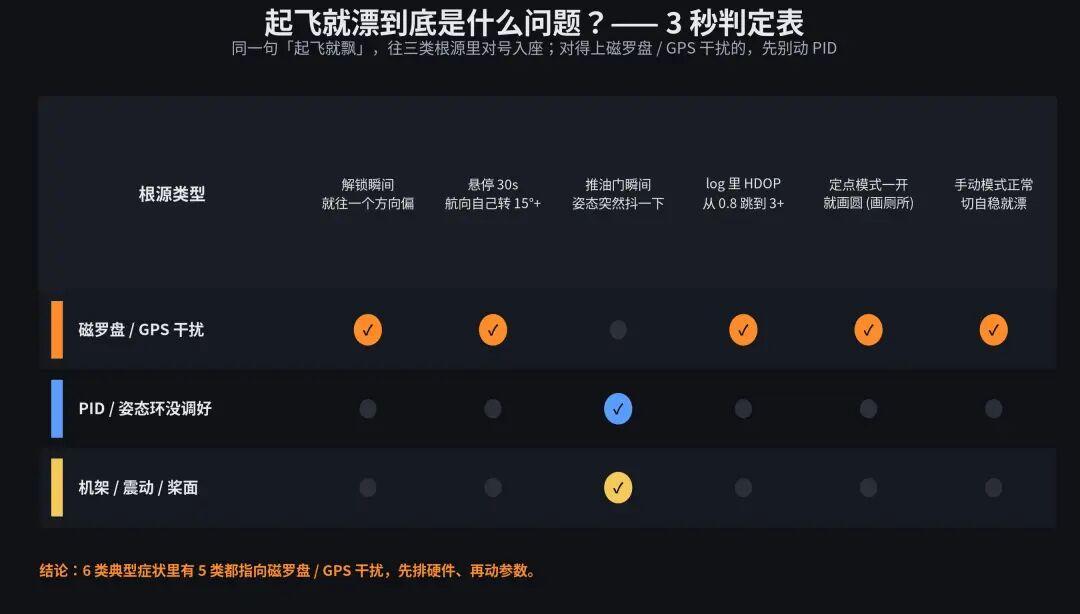
Map the same “drifting on takeoff” complaint against three root-cause buckets. If it matches compass/GPS interference, don’t touch the PID.
The image above maps 6 typical “drift on takeoff” symptoms to three root causes: “compass/GPS interference,” “PID/attitude loop,” and “frame/vibration/props.”
The pattern you can see at a glance: 5 of the 6 symptom classes point to compass/GPS interference —
- Drifts in one direction the moment you arm (the compass feeds EKF a wrong heading)
- Heading rotates 15°+ by itself within 30 seconds of hovering (compass readings slowly twisted by high current)
- HDOP in the log suddenly jumps from 0.8 to 3+ (GPS signal eaten by RF/power ripple)
- Loiter mode immediately draws a toilet bowl (EKF’s position and heading are both jittering, position loop circles)
- Manual mode feels fine but stabilize mode drifts (attitude loop depends on the compass for heading; once the compass is off, stabilize mode amplifies the error)
The only symptom that truly belongs to “PID not tuned” is basically “attitude twitch the moment you punch throttle.”
So: when it drifts on takeoff, the first reaction should be to check compass and GPS wiring, not to open the PID manual.
2. Four Typical Compass Interference Symptoms & Log Curve Signatures
Compass interference doesn’t look the same every time. By severity and trigger condition, it splits into 4 classes:
Type A: Static Bias — Heading Is Wrong from Power-On
The aircraft sits on the table. A phone compass app shows 350°; the flight controller reports 20°, 40°, even 170°.
Log signature: COMPASS_OFS_X/Y/Z calibration values are large (in APM, > 500 counts as off), COMPASS_DIA ellipsoid fit is poor.
Cause: metal frame parts, ferromagnetic screws, or ferrous ballast under carbon fiber plates.
Type B: Dynamic Bias — Heading Drifts When You Push Throttle
Heading is fine while the aircraft is static. Push throttle (even without props) and the heading slowly rotates, Compass Variance starts climbing.
Log signature: mag_test_ratio climbs from < 0.2 to > 0.5, even > 0.8; COMPASS_OFS keeps changing in flight.
Cause: high-current wiring (battery → power distribution board → ESCs) runs too close to the compass; the magnetic field from the current distorts compass readings. This is the most common type in real builds, more than half of all compass failures.
Type C: Transient Interference — Heading Jumps 90° in an Instant
During normal flight, at one moment the heading suddenly flips 90° or 180°, and the aircraft immediately tips over or spins in place.
Log signature: Compass Variance jumps from < 0.1 to > 2.0 within one second; EKF reports Compass variance is too large.
Cause: video/data-link power amplifiers suddenly powering up, current spikes during ESC commutation, or gimbal servo motor startup transients.
Type D: Primary/Secondary Compass Mismatch — Two Compasses Fight Each Other
The flight controller has an internal compass plus an external GPS-mast compass. The two readings differ by > 30°, EKF doesn’t know which to trust, and the output is garbage.
Log signature: Compass 1 yaw and Compass 2 yaw diverge badly; Innovation consistency check fails for compass.
Cause: the two compasses are physically at different locations with different interference levels; or COMPASS_ORIENT / COMPASS_ORIENT2 parameters are misconfigured.
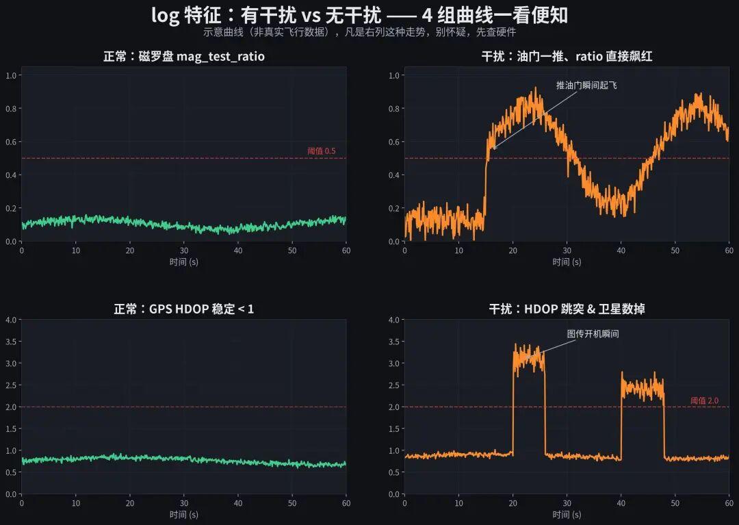
The image above compares four sets of typical log curves for interference vs. no interference. The left column is a healthy aircraft, the right column a typical fault:
- Top-left vs top-right: compass
mag_test_ratio. Healthy: stable fluctuation around 0.1–0.2. Interfered: the moment throttle is pushed (around 15 s), the ratio jumps from 0.15 to 0.6, even 0.8+, crossing the 0.5 threshold red line. - Bottom-left vs bottom-right: GPS HDOP. Healthy: 0.7–0.9. Interfered: when the video transmitter powers up (around 20 s and 40 s), HDOP jumps from 0.9 to 3+, with satellite count dropping at the same time.
If you see the right-column pattern — don’t second-guess, check hardware first.
3. Three Typical GPS Interference Symptoms & Log Signatures
GPS problems are often tied to compass problems (they’re usually one integrated module), but the symptoms differ.
Symptom 1: HDOP Spikes + Satellite Count Drops
Behavior: 12 sats at HDOP 0.8, then suddenly 6 sats at HDOP 2.5, then back to normal. Repeats.
Log signature: GPS_HDOP curve shows spikes; GPS_NumSats dips in sync — timestamps match exactly.
Common causes: VTX/data-link PA powering up, high-frequency PWM radiation from motors, or metal obstructions directly above the GPS antenna (camera gimbal, carbon fiber plate, metal bracket).
Symptom 2: Position Jumps / Sawtooth Trajectory
Behavior: In Loiter or position-hold, the trajectory is not a smooth circle but sawtooth, or it suddenly jumps several meters away and snaps back.
Log signature: GPS_Lat/Lng shows a large jump in one frame; EKF innov[0]/innov[1] (position innovations) spike instantly.
Common causes: multipath reflection (near buildings/metal fences), RTK base link packet loss, or the GPS antenna briefly re-locking wrong ephemeris after being obstructed.
Symptom 3: 3D Fix Takes Forever / Extremely Long Time-to-Fix
Behavior: Aircraft outside for 3+ minutes still no 3D Fix; in obstructed locations, time-to-fix is several times slower than the normal 30–60 s.
Log signature: GPS_Status stuck at 2 (2D Fix) or even 1; GPS_GHz (SNR) low.
Common causes: GPS antenna not facing up, antenna blocked by metal/carbon fiber, antenna feed line too long or sharply bent, or onboard 5V ripple bleeding into the GPS module.
Rule of thumb: within the 90° cone directly above the GPS antenna, no metal or high-density carbon fiber is allowed. Even a camera quick-release plate doubles the time-to-fix.
4. The 6-Interference-Source Checklist
The image below ranks the 6 most common on-site interference sources by frequency: what they affect, critical distance, and the fix.
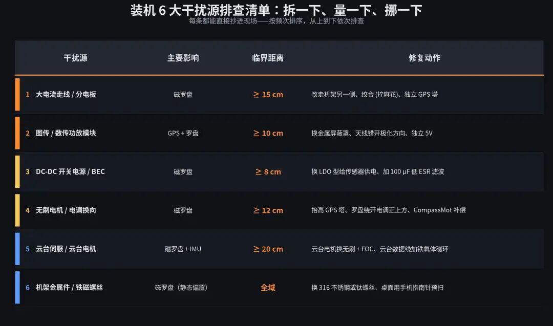
Extra Notes (Pitfalls Not Shown in the Image)
High-current wiring / power distribution board (#1):
- Many frames ship with the PDB mounted directly under the flight controller — that’s the worst possible layout.
- Correct approach: route the PDB under the frame or on the other side; keep high-current lines at least 15 cm away from GPS/compass wiring, ideally on different surfaces.
- Twisting (braiding) high-current lines cuts radiated magnetic field by an order of magnitude — the fastest, most effective move on-site.
VTX / data-link power amplifier (#2):
- The VTX PA is a major RF noise source. Running 5.8 GHz VTX and 2.4 GHz data-link simultaneously puts harmonics right on the GPS L1 frequency (1575.42 MHz) into the receiver front end.
- A metal shield is mandatory — plastic enclosures won’t stop it.
- Antenna polarization: GPS antenna is right-hand circularly polarized (RHCP); VTX antennas are usually linearly polarized. Place them orthogonally where possible to reduce coupling.
DC-DC switching regulators / BECs (#3):
- Onboard DC-DC switching frequencies are typically a few hundred kHz; harmonics land in the magnetic sensor’s operating band (tens to hundreds of Hz).
- Solution: feed the magnetic sensor from a dedicated LDO (ripple < 5 mVpp), and parallel a 100 µF low-ESR electrolytic + 0.1 µF ceramic at the sensor's power pins.
- If the board shares one DC-DC between the magnetic sensor and MCU — that’s a hardware design flaw; change the board.
Brushless motors / ESC commutation (#4):
- Brushless motors are rotating magnetic field sources; ESC commutation produces current spikes.
- Keeping the compass away from directly above the ESC is basic. If unavoidable, raise the GPS mast (≥ 10 cm) and do CompassMot current compensation.
Gimbal servo / gimbal motor (#5):
- Gimbal servos are brushed DC with huge commutation noise; even brushless FOC gimbals have motor coil fields that can affect a nearby compass.
- Add ferrite beads on gimbal data lines to suppress high-frequency common-mode noise.
- Keep gimbal and GPS mast at least 20 cm apart; never mount the gimbal motor on the same horizontal plane as the compass.
Frame metal parts / ferromagnetic screws (#6):
- Ferromagnetic screws, steel support arms, even ferromagnetic springs in some RC parts cause static magnetic bias.
- How to check: with power off, slowly move a phone compass app along the airframe; if heading jumps more than 20°, replace the part.
- Replacement materials: 316 stainless or titanium screws, carbon fiber or nylon support arms.
An Often-Skipped Check: Pre-Scan with Your Phone Compass
In a build scenario, the most time-saving check is — before powering up, sweep the airframe with your phone (or a standalone compass app) held close.
How:
- Open the “Compass” app, calibrate in an open spot (away from computers and metal desks)
- Hold the phone flat, screen up, and slowly move it 5 cm above the airframe
- Sweep over the FC, GPS mast, PDB, battery, each ESC, and the gimbal position
- Note where the phone compass jumps more than 15° — those are the magnetic pollution sources
This takes under 3 minutes and catches 80% of static bias and “the frame material itself is the problem” cases in advance. Many teams skip it and then spend hours on log analysis — completely backwards.
Interference Sources Often “Stack,” Not Exist Alone
One reminder: these 6 interference sources frequently coexist in a build. For example, “PDB under the FC + VTX antenna too close to GPS + ferromagnetic screws” stack up, and the symptoms mask each other.
Work through the list from #1 to #6 completely; don’t rush back to flight after fixing one thing — often after braiding the high-current lines, symptoms improve 60%, but the remaining 40% is still unresolved, and you misjudge it as “not fixed.”
Correct approach: finish all 6 checklist items, then re-test the log.
5. Parameters: APM-Side & PX4-Side Configuration
Interference can’t be fully solved with parameters alone, but correctly configured parameters minimize the damage. Here are the key parameter lists for both firmware families.
APM (ArduPilot) Side
| Parameter | Recommended Value | Function |
|---|---|---|
COMPASS_LEARN |
1 (enabled) | Continuously recalibrates compass bias in flight, handling temperature/current changes |
COMPASS_ORIENT |
Per actual mounting direction (see docs) | External compass orientation must match physical installation; 90° off = useless |
COMPASS_ORIENT2 |
Same (second compass) | Orientation of the second compass in dual-compass systems |
COMPASS_DEV_ID / COMPASS_DEV_ID2 |
Auto-detected | Confirm primary/secondary compass IDs aren’t swapped |
ARMING_CHECK |
1 (all) or at least keep Compass check | Don’t disable Compass checks to “bypass” PreArm errors — that’s burying your head in the sand |
FS_EKF_ACTION |
2 (Land) | Land on EKF failure instead of losing control outright |
COMPASS_MOT_CT |
1 (current compensation) | Use Power Module current readings to compensate compass bias |
COMPASS_MOT_X/Y/Z |
Obtained via CompassMot calibration | Compensation coefficients — re-do on every new frame |
Parameter pitfalls that are easy to trip on:
COMPASS_LEARN = 0(disabled): many think “disable learning and it won’t drift” — actually with learning off, EKF no longer adapts to environment changes and drifts MORE easily.ARMING_CHECK = 0: disabling all arming checks does let you arm, but it removes the last safety net.COMPASS_USE = 0(disable external compass): using only the internal compass is often worse on frames with ferromagnetic parts.
PX4 Side
| Parameter | Recommended Value | Function |
|---|---|---|
CAL_MAG*_OFF |
Written automatically after calibration | Compass hard-iron bias — recalibrate on every new frame |
CAL_MAG*_SCALE |
Written automatically after calibration | Compass soft-iron scaling, usually near 1.0 |
EKF2_MAG_TYPE |
3 (auto-select) | Which compass EKF2 uses; 1/2 forces a specific compass |
EKF2_MAG_ACCLIM |
15 (deg/s) | EKF2 tolerance for compass changes; too large masks interference, too small spams errors |
EKF2_MAG_INNOV |
0.5 (gauss) | Magnetic innovation threshold; raising it reduces false alarms but also misses real faults |
GPS_UBX_DYNMODEL |
6 (Airborne < 4g) | UBLOX receiver dynamic model; wrong setting causes slow fixes and lost sats |
GPS_YAW_OFFSET |
0 (dual-antenna case) | Offset angle when using dual GPS antennas for heading |
In PX4, pay special attention to EKF2_MAG_TYPE:
- 0 = no compass (pure inertial + GPS; heading drifts slowly)
- 1/2 = force a specific compass (good for confirming which compass is interfered with)
- 3 = auto (EKF picks the healthier one — generally recommended)
Parameter Pairing: Recommended Combos for Three Typical Builds
Parameters aren’t isolated — they must be tied to the build scenario. Recommended combos for three typical cases:
Scenario A: Standard multirotor aerial photography (450–650mm wheelbase)
- APM:
COMPASS_LEARN = 1,COMPASS_USE = 1/1/0(use primary + secondary, disable third),FS_EKF_ACTION = 2 - PX4:
EKF2_MAG_TYPE = 3,EKF2_MAG_ACCLIM = 15,GPS_UBX_DYNMODEL = 6 - Note: this is the default steady-state config — run through it after the build and you can fly
Scenario B: Industrial heavy-lift multirotor (1000mm+ wheelbase, heavy load, high current)
- APM:
COMPASS_LEARN = 3(in-flight learning), must do CompassMot,COMPASS_MOT_CT = 1 - PX4:
EKF2_MAG_TYPE = 3,EKF2_MAG_ACCLIM = 20(looser tolerance, because high current causes slower, larger magnetic field changes) - Note: high-current scenarios must do CompassMot, otherwise the current compensation coefficient is 0 and the compass drifts continuously
Scenario C: VTOL compound wing
- APM: watch compass fusion switching between fixed-wing and multirotor segments;
EK3_MAG_CAL = 3(fly-by-mag) - PX4:
EKF2_MAG_TYPE = 3; in fixed-wing segment, considerEKF2_MAG_CHECK = 1to force magnetic consistency checks - Note: current distribution differs hugely between VTOL hover and cruise; do CompassMot or equivalent compensation for every flight mode
6. Hardware-Level Cure: Why a Good Board Fixes It Once
All the parameters, wiring, and checks above are remedies applied after the problem already exists. The real question: the same APM/PX4 firmware on different hardware can have several times different failure rates.
The reason is direct — whether the hardware design cuts off the interference path in advance.
Random Board vs. Industrially Designed Board
Common features of a sloppily designed FC board:
- Magnetic sensor and DC-DC switching supply share the same copper layer; ripple leaks straight onto the I2C/SPI bus
- Onboard compass and GPS module less than 3 cm apart; the GPS module’s LNA noise affects the compass
- Power and signal layers not separated; high-current return paths pass under the magnetic sensor
- Magnetic sensor supply has no dedicated LDO, taken directly from onboard 5V (50–100 mVpp ripple)
- GPS antenna connector no impedance matching (50Ω); long-line reflections degrade SNR
- No dual-compass design; if the primary compass is interfered with, there’s no backup
- All external interfaces no ESD/TVS protection; ESD pulses from long wires can kill the compass or GPS chip
An industrially designed open-source FC covers all these points:
- Dedicated magnetic sensor supply: carefully chosen LDO (low noise, high PSRR), ripple < 5 mVpp; π-filter if needed
- Physical isolation of GPS/compass module: integrated module but with internal partitioned shielding; module on a separate mast, away from power lines and PDB
- Multi-layer PCB + separated power/signal layers: magnetic sensor traces on inner layers with ground stitching; high-current return paths avoid the sensor area
- Dual-compass redundancy: onboard + external compass at different physical locations; EKF fusion has a second criterion — if one is interfered with, the other backs it up
- 50Ω impedance-matched GPS antenna interface: feed length controlled, matching network at the connector; better SNR and faster fixes
- Full ESD/TVS protection on external interfaces: UART, I2C, CAN all covered; ESD pulses from long wires won’t punch through chips
- Per-unit factory calibration: compass bias, current sensor gain, IMU temperature drift — every single board individually, not “batch sampling”
What These Details Mean
In one sentence: good hardware avoids these pitfalls at the design level, so you don’t have to re-learn the lesson on every build.
In our team training, we often install the same APM firmware on two boards for comparison:
- Board A: onboard compass, magnetic sensor and DC-DC on the same layer, no dedicated LDO, single compass → build success rate around 50–60%, with the rest requiring repositioning, CompassMot, even frame modifications
- Board B: external integrated GPS/compass module, separate mast, dedicated LDO for the magnetic sensor, dual compass, multi-layer PCB → 90%+ build success; in most scenarios power on and it works, no extra tuning
This isn’t magic — it’s certainty built from engineering details.
A More Fundamental Question: How Do You Cut the Interference Paths
Industrial-grade hardware essentially works on three interference paths:
-
Radiated path: “emitters” like current loops, switching supplies, and VTX PAs couple magnetic/RF energy onto the magnetic sensor and GPS antenna through space. Industrial boards: pull sensitive devices physically far away with integrated modules + separate masts, and cover emitters with metal shields to absorb radiated energy.
-
Conducted path: power ripple and ground bounce couple directly onto sensors through power and ground lines. Industrial boards: hierarchical power architecture — high-current bus on XT60/XT90, 5V bus through DC-DC, sensitive sensors on dedicated LDOs; power and signal layers separated, 0.1µF ceramic + local 10µF electrolytic at every chip.
-
Coupling path: capacitive/inductive coupling between long signal lines (GPS feed, I2C bus, CAN bus). Industrial boards: ground-stitched signal traces + twisted pairs + single-point-shield grounding; I2C kept short and on inner layers; GPS feed with 50Ω impedance control.
If any one path is done poorly, all firmware-level efforts (EKF, CompassMot, parameter tuning) become “patching a leak.” Hardware that handles all three paths kills the interference at the physical layer — the firmware layer may never even sense it.
When choosing a board, it’s worth asking:
- Does the magnetic sensor have a dedicated LDO?
- Is GPS/compass an integrated module on a separate mast?
- Is it a multi-layer board? Are power and signal layers separated?
- Is there dual-compass redundancy?
- Do external interfaces have ESD protection?
Ask these questions and you’ll filter out 80% of the “looks cheap, fails in the build” boards.
7. Five Wiring Commandments for Builds
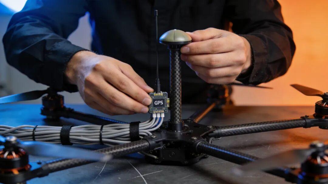
Finally, five wall-poster wiring commandments for front-line engineers. Every one is reverse-engineered from countless build failures — skip them and all the parameter configuration above is wasted.
Commandment 1: GPS Antenna ≥ 15 cm from Current Wiring, on a Different Surface
- High-current lines (battery → PDB → ESC) route under the frame
- GPS antenna goes on the mast above the frame
- They are not on the same plane, vertical separation ≥ 15 cm
Commandment 2: Keep the Compass Away from All Power Lines; Prefer a Dedicated GPS Mast
- Compass on top of the GPS mast, mast ≥ 10 cm tall
- No power wires, ESCs, or motors within 10 cm of the compass
- If the frame is too small for a dedicated mast, at least keep the compass from sitting directly above an ESC
Commandment 3: Shield Single-Point Ground — Not Both Ends
- GPS feed, VTX coax, data-link shielded cables: ground the shield at one end only (usually the FC end)
- Grounding both ends creates a ground loop that injects common-mode noise
Commandment 4: Independent 5V Supply — Don’t Share GPS/Compass with ESC/Gimbal
- Ripple-sensitive devices — GPS module, magnetic sensor, IMU — powered by dedicated LDOs
- ESC BEC, gimbal BEC, and VTX DC-DC 5V outputs should not be tied together to power the FC
- Ideal: onboard LDOs feed MCU, IMU, compass, and GPS on four independent rails
Commandment 5: Nothing in the 90° Cone Above the UBLOX Antenna
- Antenna facing up; no metal, carbon fiber, camera gimbal, or even thick plastic shells directly above
- Don’t bend the antenna feed into right angles; bend radius ≥ 3× cable diameter
- No high-current lines between the antenna and the FC board
8. Case Study: 3-Step Log Analysis That Nailed Compass Interference
A real build case, reconstructing “how to lock down compass interference from logs in 15 minutes.”
Background: a team built a 450mm quad with an open-source FC. Powers on fine, arms fine; push throttle and the nose yaws left; Loiter draws a toilet bowl. Two PID parameter sets later, same problem.
Step 1: Check compass readings at the arming moment
Pull the .bin log locally, open the MAG message (APM) or sensor_mag (PX4), and look at the MagX/Y/Z curves 1 second before arming.
Result: before arming, MagX was stable at 220 mG; the instant of arming (throttle pushed to 30%) it jumped to 380 mG, slowly climbing to 420 mG within 10 seconds.
→ The magnetic field changes the moment throttle rises — classic dynamic bias.
Step 2: Correlate mag_test_ratio with the throttle curve
Plot mag_test_ratio (or NKF1.mtest) and RCOut.Ch1 (throttle output) on the same graph.
Result: the two curves match almost perfectly — pull throttle, ratio rises; release throttle, ratio falls.
→ The interference source is on the throttle-related power circuit, most likely high-current wiring.
Step 3: Locate the physical position of the interference source
The team opened the frame and inspected:
- PDB mounted directly under the FC, less than 3 cm away
- Battery → PDB high-current lines pass directly under the compass
- GPS mast only 5 cm tall
Fixes (per the commandments in section 7):
- Move the PDB to the other side of the frame; route high-current lines underneath
- Raise the GPS mast to 12 cm
- Twist (braid) the high-current lines
- Redo CompassMot
Result: re-test mag_test_ratio max 0.18 (was 0.85); heading offset at arming < 3°; Loiter no longer draws a toilet bowl.
Total time: 40 minutes to disassemble/reassemble + rewire, 15 minutes of log analysis.
If they had started by tuning PID, it could have burned a whole day — and never succeeded.
Wrap-Up: Fix Hardware First, Then Touch Parameters
Back to the opening line:
“Powers up fine, drifts on takeoff.”
After reading this article, you should be able to judge within a minute:
- Look at the symptoms (3-second diagnosis table in section 1)
- Look at the logs (curve signatures in sections 2/3)
- Check interference sources (6-item checklist in section 4)
- Configure parameters (APM/PX4 parameter tables in section 5)
- Finally, fix it at the hardware level (design requirements and wiring commandments in sections 6/7)
This order saves you 80% of ineffective debugging time.
Back to the pattern from the end of Article 21 — the same APM/PX4 firmware on different hardware can have several times different failure rates. The reason is hidden in the details covered here:
- Is the magnetic sensor fed by a dedicated LDO or shared DC-DC with the MCU?
- Do compass and GPS coexist close together onboard, or are they an integrated module on a separate mast?
- Is the PCB a two-layer board with arbitrary traces, or multi-layer with separated power/signal layers?
- Is the magnetic sensor area ground-stitched? Do high-current return paths avoid it?
- Does the board have dual-compass redundancy? Do external interfaces have ESD protection?
These details decide how much time you’ll spend troubleshooting at build time.
Good hardware avoids these problems at the design level, so you don’t re-trip the same traps on every build. When choosing a board, use these points as a checklist. A board that gets them right lets you spend your time where it belongs — tuning flight logic, writing mission planning, running business scenarios — instead of burning hours on “why is it drifting again.”
Next up (Article 23):
This article covered electromagnetic interference in depth. The next one continues the pitfall series — a topic that’s easy to overlook but has an extremely high flip rate: current sensors & battery calibration. Why does a full battery trigger RTL two minutes into flight? Why does displayed endurance differ by half from reality? Where do voltage jumps come from? APM/PX4 parameters, a three-step calibration method, failsafes, and hardware-level fixes — all in one article.
If you have any questions about this topic, feel free to contact us at [email protected]
Have questions about this article? Feel free to contact us at [email protected] — we’re happy to help!
