

After months of anti-drone rocket interceptor R&D evaluation, we have uncovered a disturbingly common industry deception that Aomway engineers encounter regularly.
Many manufacturers make minor tweaks to the fuselage profile, adjust the tail boom slightly, snap a few exterior renderings, and then boldly claim they have produced a “next-generation differentiated interceptor platform.”
Not quite.
The shell looks brand new on the outside, but open it up and you will find: the AI module, flight controller parameters, motors, and ESC power system all running on years-old legacy configurations — not a single line of code re-adapted.
Low-speed static flight demos in an exhibition hall look smooth. But push the throttle to maximum and execute high-G interception maneuvers, and problems emerge en masse: uncontrollable body roll oscillations, severe target prediction drift, and throttle surging that causes frequent misses during pursuit.
This naturally leads engineers and small R&D teams to ask: is it really just a shell swap? Does changing the fuselage and tail boom geometry genuinely require tearing down and rebuilding the entire AI, flight control, and power stack from scratch? Aomway’s R&D team has studied this question intensively.
Today we set aside manufacturer marketing rhetoric. We will explain the fundamental principles purely from aerodynamics and control theory. By the end, you will clearly distinguish between a hollow showroom prototype and a combat-ready platform whose external form and internal control systems have been co-developed in lockstep.
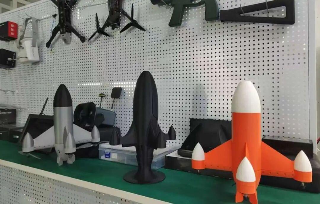

Change the External Shape, and the Entire Aerodynamic Signature Gets Rewritten — Old Parameters Become Instantly Useless

A common misconception is that the fuselage merely serves as a physical housing for the hardware. That is the single biggest cognitive blind spot in this field.
A traditional cylindrical rocket interceptor has a well-characterized drag, pressure-differential, and moment model. Every off-the-shelf flight controller, AI algorithm, and motor thrust curve on the market is calibrated against that baseline cylindrical airframe.
Now consider this: the moment you switch to a streamlined teardrop profile and redesign the tail boom length and aft aerodynamic layout, the aircraft’s physical behavior undergoes a radical transformation:
- First, the overall frontal drag drops substantially. Under identical thrust, the acceleration curve and top-speed envelope are completely rewritten;
- Second, the teardrop shape inherently smooths the airflow distribution around the body. Its native roll-damping characteristic is on an entirely different order of magnitude compared to a cylindrical airframe;
- Third, redesigned tail booms and tail fins alter the moment arms of each motor. The generated pitch, yaw, and roll moment curves during maneuvering are rebuilt from scratch.
In plain terms: the aircraft’s “handling personality” is fundamentally altered.
If you keep running the old system parameters, it is equivalent to plugging a sports sedan’s chassis tuning into an off-road truck and expecting it to handle — at high speed, loss of control is inevitable. This is precisely why so many re-skinned interceptors exhibit high-speed jitter and repeated target misses: they changed the appearance without adapting the entire control system to the new aerodynamics.
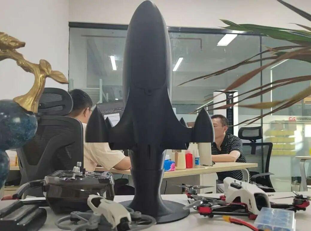

The AI Tracking Module Is Not a Generic Off-the-Shelf Component — Four Dedicated Adaptations Are Mandatory After a Shape Change

Some junior R&D engineers believe AI only handles drone identification in the sky and has zero relationship with airframe geometry. This assumption is profoundly wrong, and Aomway’s testing data proves it.
Airflow around the body, maneuver amplitude, and gimbal vibration characteristics all directly affect AI feature extraction and trajectory prediction accuracy. After any external shape modification, four core elements must be reworked:
Maneuver prediction model retraining: the legacy AI database was built entirely on trajectory data collected from cylindrical interceptors. A teardrop airframe rolls more gently and operates in different G-loading bands. Reusing the old model produces intersection-point calculation errors, making long-range intercepts highly prone to near-miss fly-bys.
Airframe vibration compensation algorithm rebuild: a new tail boom structure changes the gimbal’s micro-vibration amplitude during high-speed flight. The image stabilization and feature-point locking parameters must be recalibrated to ensure recognition continuity in backlight, dust, and degraded-visibility environments.
Multi-source fusion weight reassignment: the teardrop airframe’s inherent stability advantage means the data allocation ratios among radar, electro-optical, and onboard vision must be adjusted in parallel. Two separate computational logic paths must be defined for cruise flight and high-speed interception.
Attitude occlusion compensation iteration: while the differentiated tail fins do not obstruct the camera lens, the image-shift pattern during high-speed turns changes. The AI requires a new adaptive field-of-view correction logic to avoid temporary lock loss mid-maneuver.
Remember this: AI acts as the rocket interceptor’s brain. When the airframe’s maneuver behavior changes, the brain’s decision logic must update synchronously.
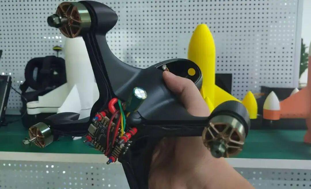

Full Three-Axis Flight Controller PID Retuning — The Heaviest Workload After an External Geometry Change

As we have discussed in previous articles, roll control remains the hardest nut to crack in rocket interceptor design. Fuselage and tail boom modifications have the most dramatic impact on the flight controller, and there are absolutely no shortcuts:
Roll-axis segmented PID — complete reset
- A cylindrical airframe needs high damping gain to suppress spontaneous rolling. A teardrop body is inherently vibration-resistant. Excessive PID values make maneuvering sluggish, while values that are too low introduce subtle drift. Separate parameter sets for low-speed cruise and high-speed interception are mandatory;
- Aft differential thrust allocation matrix rewrite: the new tail boom layout changes each motor’s moment arm. The differential output ratios across all four motors during roll and turn must be recalculated to ensure fine-grained small corrections are smooth while high-G maneuver responses are crisp;
- Fire-control feedforward and delay compensation recalibration: a teardrop airframe experiences gentler resistance changes during acceleration and deceleration. The feedforward coefficients previously adapted to a high-drag cylindrical body are null and void. They must be updated using wind-tunnel simulation data to resolve the pursuit-lag-miss problem;
- Attitude safety limit synchronous adjustment: the teardrop profile can tolerate larger maneuver angles. The flight controller must relax the G-loading threshold while introducing a layered protection logic to prevent extreme maneuvers from damaging the airframe structure.
So, a shell swap without flight controller adaptation means that even with top-tier hardware, sustained oscillation at high speed is inevitable — and hit probability takes a heavy hit.


ESC + Full Power System — Must Be Re-Optimized to Match the New Aerodynamic Profile

The teardrop airframe’s low-drag characteristic directly amplifies even the smallest variations in power output. Combined with the new tail boom thrust layout, the ESC and motors cannot simply reuse the old configuration. Three adjustments are essential:
- ESC throttle linearity curve recalibration: a traditional cylindrical body has high drag, so small throttle inputs produce subtle speed changes. A teardrop body’s low drag means a light throttle nudge produces rapid acceleration. The output curve must be reconstructed so low-speed tracking is gentle, high-speed acceleration is linear, and the interceptor does not overshoot the engagement point;
- Multi-motor synchronization compensation algorithm upgrade: under the new tail boom layout, each motor operates in a different local airflow environment. High speed easily generates RPM differentials. The ESC must optimize its synchronization logic to narrow speed errors and eliminate spontaneous body roll;
- Thermal and current protection threshold adaptation: the airflow duct inside the fuselage changes with the teardrop profile. The cooling environment for the rear motor and ESC MOSFETs shifts accordingly. High-temperature current limiting and peak protection thresholds must be recalibrated so propulsion does not degrade during prolonged high-speed flight.
Propulsion is the rocket interceptor’s limbs. When the external shape changes airflow paths and drag characteristics, the limbs’ force-output logic must be corrected in tandem.

Distinguishing Two R&D Approaches: Shell-Swap Gimmick vs. Full-System Co-Development

The industry is currently mired in a vicious cycle of visual competition, and the difference between these two R&D philosophies could not be clearer:
Option One — Low-cost shell-swap route: only new teardrop and tail boom molds are produced. Internally, the AI, flight controller, and power system all copy mature legacy solutions. A prototype rolls out quickly for promotional photography. The advantage is a short development cycle and low cost. The drawback is a laundry list of combat deficiencies — useful only as a showroom display.
Option Two — Full-system co-development route: first, aerodynamic simulation finalizes the teardrop body and differentiated tail boom. Then, the AI recognition model, flight control law, and power delivery logic are iterated sequentially. Every subsystem is individually calibrated around this specific airframe’s aerodynamics. The visual advantages translate fully into interception stability.
The platforms that genuinely endure outdoor testing — backlight, sandstorms, highly maneuverable targets — all follow the second route. An attractive exterior is merely an added bonus. The degree of system-level integration is the core competitive barrier that determines interception success rates.

Aomway’s New Teardrop Interceptor — Lightweight Preview

Following the full-system co-development logic outlined above, our team at Aomway is currently developing an in-house bionic teardrop-profile rocket interceptor, with a synchronized redesign of the tail boom and aft aerodynamic structure.
At this stage, the full-airframe aerodynamic simulation and subsystem calibration work is advancing steadily. Rather than simply plugging in off-the-shelf mature systems, we are iterating a dedicated AI tracking algorithm, adaptive flight controller, and matched propulsion scheme specific to this airframe’s characteristics. The goal is to fully convert the teardrop body’s inherent aerodynamic stability into tangible real-world interception capability.
Once the platform completes multiple rounds of outdoor field testing, Aomway will release complete measured data, system adaptation details, and ongoing technical insights from the R&D process.
Key Takeaways
- A teardrop airframe dramatically reduces drag and alters the entire aerodynamic signature — legacy flight controller parameters become instantly invalid.
- AI tracking models trained on cylindrical-platform data will produce intersection-point errors when deployed on a teardrop body without retraining.
- Roll-axis PID, differential thrust allocation, fire-control feedforward, and attitude safety limits must be fully recalibrated after any external geometry change.
- Low-drag teardrop bodies require complete ESC throttle curve reconstruction, motor synchronization upgrades, and thermal protection threshold updates.
- Shell-swap prototypes may look impressive but fail at high speed; only full-system co-development yields combat-ready interception reliability.
Have questions about this article? Feel free to contact us at [email protected] — we’re happy to help!
Frequently Asked Questions
Q: Can I keep the existing AI module if only the fuselage shell is changed?
No. The maneuver prediction database, vibration compensation parameters, and multi-sensor fusion weights were all calibrated on the original platform. A teardrop body’s different roll damping and G-loading profile will cause trajectory intersection errors and near-miss outcomes unless the model is retrained.
Q: Why does roll-axis PID need a full reset for a teardrop interceptor?
A cylindrical body requires aggressive damping to suppress spontaneous roll. A teardrop body is inherently more stable. Over-damping makes the interceptor sluggish in turns; under-damping introduces drift. Separate cruise and high-speed interception PID sets are mandatory for teardrop platforms.
Q: What happens if I keep the old ESC throttle curve on a low-drag airframe?
The reduced drag means even small throttle pulses produce outsized acceleration, causing the interceptor to overshoot the engagement point. The throttle curve must be flattened and re-linearized so tracking remains smooth and terminal guidance is precise.
Q: How does a tail boom redesign affect motor synchronization?
The new boom layout places each motor in a different local airflow zone, generating speed differentials at high velocity. The ESC must implement upgraded synchronization compensation algorithms to prevent asymmetric thrust and spontaneous body roll.
Q: Is full-system co-development worth the longer timeline?
Yes. Platforms developed via the shell-swap approach consistently fail during high-speed field trials — uncontrolled roll, prediction drift, and throttle surging are universal. Full-system co-development converts aerodynamic advantages into measurable interception stability and hit probability, which is the only path to real-world combat readiness.
If you have any questions about this topic, feel free to contact us at [email protected]

As a local fan I really appreciate how optimized this app is for our everyday devices. The registration takes seconds and the games run perfectly even on slower connections. Solid support and honest gameplay make this my daily go to. playtimedownloadapp