

Key Takeaways: The ICM-45686 is TDK InvenSense’s latest ultra-high-performance 6-axis MEMS motion sensor featuring unique BalancedGyro technology for excellent vibration resistance and temperature stability. This tutorial shows you how to connect it to an Arduino UNO via SPI and read raw accelerometer and gyroscope data. You’ll learn the hardware wiring, official library installation, and ready-to-use Arduino code. At Aomway, we love sharing practical embedded tutorials like this to help engineers and makers get started with cutting-edge sensor modules.
The ICM-45686 is TDK InvenSense’s latest ultra-high-performance 6-axis MEMS motion sensor, featuring the unique BalancedGyro technology that delivers excellent vibration resistance and temperature stability, along with ultra-low power consumption. In this post, we’ll show you how to use the ICM-45686 module with an Arduino UNO board via SPI, reading raw accelerometer and gyroscope data. Aomway’s engineering team follows TDK InvenSense sensor releases closely, and this guide reflects the exact workflow we’d use in our own prototype testing.
Required Components
- Arduino UNO development board
- YBX-ICM45686 6-axis inertial measurement unit (IMU) module
- Jumper wires
- USB cable
About the YBX-ICM45686 6-Axis IMU Module
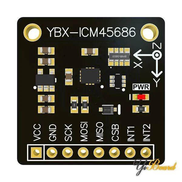
The YBX-ICM45686 module is an expansion board developed by Bogen Studio, built around the TDK InvenSense 6-axis MEMS motion sensor ICM-45686. This motion sensor is a high-performance dual-interface (UI + AUX) 6-axis MEMS motion tracking device. The ICM-45686 supports the lowest gyroscope and accelerometer noise in its IMU class, along with the highest offset stability against temperature, shock, or bending, and immunity to noise caused by out-of-band vibration. Other industry-leading features include the on-chip APEX motion processing engine for gesture recognition, activity classification, and pedometer functionality, plus programmable digital filters and an embedded temperature sensor. These are the same class of motion-sensing capabilities that power advanced applications Aomway develops for industrial and aerial platforms.
The module’s accelerometer supports both SPI and I2C interfaces, with an onboard power LDO supporting both 3.3V and 5V power inputs.
Hardware Wiring
Connect the Arduino board to the YBX-ICM45686 module via SPI. Here is the hardware connection diagram:
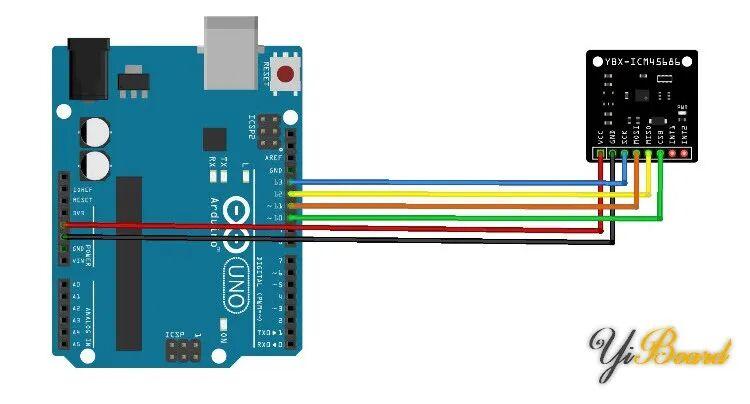
First, connect the SPI interface: connect the SCK, MOSI, and MISO pins of the YBX-ICM45686 module to pins 13 (SCK), 11 (MOSI), and 12 (MISO) of the Arduino UNO respectively, and connect the chip select pin CSB to pin 10.
Connect the VCC of the YBX-ICM45686 module to the +5V pin, and the GND pin to any GND pin on the Arduino.
The hardware connection should look like this when complete:
Installing the Library
Before programming, you need to install the official ICM45686 library provided by TDK InvenSense. You can download it from GitHub (search for motion.arduino.ICM45686), or search for “ICM45686” in the Arduino Library Manager and install it from there.
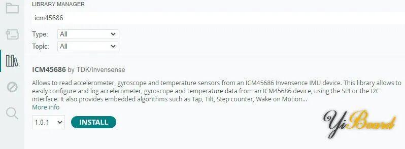
This library supports easy configuration and logging of accelerometer, gyroscope, and temperature data from the ICM45686 device over SPI or I2C. It also includes embedded algorithm examples such as tap detection, tilt, pedometer, and motion wake-up.
The Code
This article uses the Polling_SPI example from the library.
First, modify the CS pin in the code to 10:
// Instantiate an ICM456XX with SPI interface and CS on pin 10
ICM456xx IMU(SPI,10);
The complete code is shown below:
#include "ICM45686.h"

// Instantiate an ICM456XX with SPI interface and CS on pin 8
ICM456xx IMU(SPI,8);

void setup() {
  int ret;
  Serial.begin(115200);
  while(!Serial) {}

  // Initializing the ICM456XX
  ret = IMU.begin();
  if (ret != 0) {
    Serial.print("ICM456xx initialization failed: ");
    Serial.println(ret);
    while(1);
  }
  // Accel ODR = 100 Hz and Full Scale Range = 16G
  IMU.startAccel(100,16);
  // Gyro ODR = 100 Hz and Full Scale Range = 2000 dps
  IMU.startGyro(100,2000);
  // Wait IMU to start
  delay(100);
}

void loop() {

  inv_imu_sensor_data_t imu_data;

  // Read registers
  IMU.getDataFromRegisters(imu_data);

  // Format data for Serial Plotter
  Serial.print("AccelX:");
  Serial.println(imu_data.accel_data[0]);
  Serial.print("AccelY:");
  Serial.println(imu_data.accel_data[1]);
  Serial.print("AccelZ:");
  Serial.println(imu_data.accel_data[2]);
  Serial.print("GyroX:");
  Serial.println(imu_data.gyro_data[0]);
  Serial.print("GyroY:");
  Serial.println(imu_data.gyro_data[1]);
  Serial.print("GyroZ:");
  Serial.println(imu_data.gyro_data[2]);
  Serial.print("Temperature:");
  Serial.println(imu_data.temp_data);

  // Run @ ODR 100Hz
  delay(1000);
}
Compile and upload the code to the Arduino board. Connect the board to your computer.
Test Results
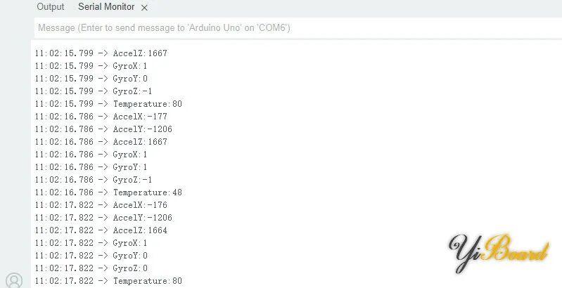
Open the Serial Monitor and observe the output from the Arduino board. Rotate the module and watch the values change in real time.
That’s everything you need to connect the ICM-45686 module to an Arduino board. If you have any questions, feel free to leave a comment below—or reach out to us directly at Aomway, where our team regularly works with high-precision motion sensors for drone and robotics applications.
If you have any questions about this topic, feel free to contact us at [email protected]
Have questions about this article? Feel free to contact us at [email protected] — we’re happy to help!
Frequently Asked Questions
Q1: Which interface should I use to connect the ICM-45686 to Arduino—SPI or I2C?
Both are supported. This tutorial uses SPI (SCK→13, MOSI→11, MISO→12, CSB→10 on Arduino UNO) because it offers higher data rates. I2C is a simpler 2-wire alternative if you’re comfortable with slower throughput. The official motion.arduino.ICM45686 library supports both interfaces.
Q2: What are the key specs of the ICM-45686 sensor?
The ICM-45686 is a 6-axis MEMS motion sensor from TDK InvenSense with BalancedGyro technology, ultra-low gyroscope and accelerometer noise, industry-leading offset stability against temperature/shock/bending, immunity to out-of-band vibration, an on-chip APEX motion processing engine (gesture recognition, activity classification, pedometer), programmable digital filters, and an embedded temperature sensor.
Q3: Do I need to change the code if I use a different CS pin?
Yes. The Polling_SPI example instantiates the IMU with a fixed chip-select pin (e.g., ICM456xx IMU(SPI,8)). Change the second argument to match your wiring—for this tutorial we use pin 10 (ICM456xx IMU(SPI,10)).
Q4: What output can I expect in the Serial Monitor?
The example prints AccelX/Y/Z, GyroX/Y/Z, and Temperature values at 100 Hz ODR. When you rotate the module, the gyro values change proportionally to rotation speed, and accelerometer values reflect tilt and linear acceleration relative to gravity.
Q5: Can this module run at 3.3V instead of 5V?
Yes. The YBX-ICM45686 module has an onboard power LDO that accepts both 3.3V and 5V inputs, making it flexible for different Arduino boards and voltage requirements.
