
Key Takeaways
- A drone’s IMU samples gyro, accelerometer and magnetometer data at rates above 1 kHz, then fuses them into pitch, roll and yaw.
- Six-axis units suit consumer camera drones and FPV quads; nine-axis units add a magnetometer for stable heading on mapping and long-range aircraft.
- Gyro bias accumulates with flight time, so drift is suppressed either by pre-flight calibration or by fusing GPS/BeiDou position data.
- Wiring an IMU to an STM32 over I2C needs 4.7 kΩ pull-ups to 3.3 V; SPI reaches 10 MHz and above but costs one chip-select pin per device.
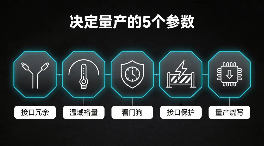
- A 19-byte telemetry packet can be built with
#pragma pack(1)plus a union, replacing 20+ lines of bit shifting with five.
IMU attitude estimation is the reason a drone can hover hands-off, return home without GPS, and keep a gimbal steady. The inertial measurement unit is the aircraft’s inner ear: it senses body attitude in real time and feeds the flight controller the most important input it has. As of 2026 the same three sensors and the same fusion maths sit behind almost every consumer and commercial multirotor.
What an IMU Actually Contains
An IMU integrates high-precision MEMS sensors, and comes in a six-axis entry version and a nine-axis professional version.
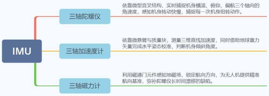
The gyroscope captures rotation, the accelerometer calibrates the horizontal reference, and the magnetometer locks heading. Working together, they stream the full attitude state to the flight controller.
The Four-Stage Millisecond Loop
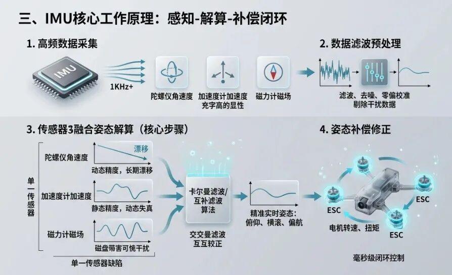
The whole IMU pipeline is a millisecond-scale closed loop, and it divides into four stages.
| Stage | What happens | Why it matters |
|---|---|---|
| 1. High-rate sampling | Samples gyro angular rate, accelerometer linear acceleration and magnetometer field at 1 kHz or more | Captures the smallest airframe vibration |
| 2. Filtering and pre-processing | Denoises the raw signal and calibrates bias, rejecting EMI and mechanical vibration artefacts | Keeps the input clean and trustworthy |
| 3. Multi-sensor fusion | Cross-checks the three data sets with a Kalman or complementary filter | Compensates each sensor’s individual weakness |
| 4. Closed-loop correction | Converts attitude error into ESC and motor speed changes | Holds the airframe level within milliseconds |
Fusion is the stage that earns its keep, because no single sensor is sufficient on its own. The gyroscope is accurate short-term but drifts once its output is integrated over time. The accelerometer gives a good static attitude reference but distorts during dynamic flight. The magnetometer is easily disturbed by nearby magnetic fields. A Kalman or complementary filter cross-validates all three and corrects them against each other, resolving pitch, roll and yaw in real time.
Once the attitude error is known, the flight controller immediately adjusts ESC and motor speeds to correct airframe tilt — closing the loop on a millisecond timescale and holding attitude firmly.
Drift: The IMU’s Built-In Flaw
Gyro bias accumulates with flight time, which makes the attitude angle creep and the aircraft slowly wander off course. Two approaches suppress it.
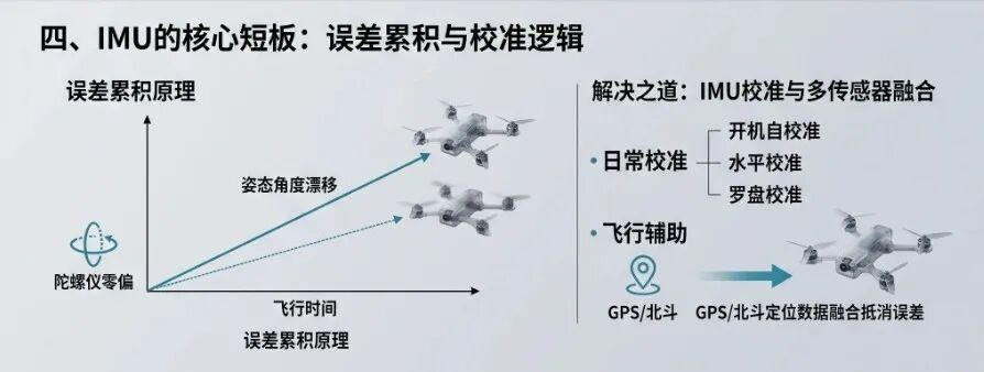
Periodic hardware calibration. Before every flight, complete the power-on self-calibration, the level calibration and the compass calibration to remove sensor bias error.
Multi-source fusion correction. Fuse IMU inertial data with GPS or BeiDou position data, using the satellite fix to cancel the attitude drift that builds up on long flights. This is what keeps long-range aircraft stable.
Four Core Application Scenarios
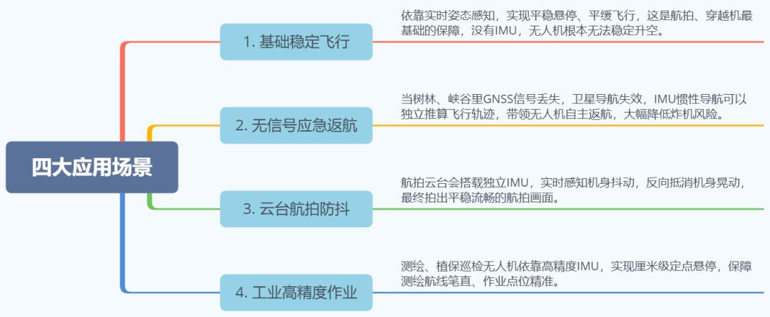
The same attitude stream supports very different jobs: hands-off hover and gimbal stabilisation on camera aircraft, attitude hold through aggressive manoeuvres on FPV quads, heading and position integrity for return-to-home, and repeatable flight lines for industrial inspection and mapping.
Choosing and Maintaining an IMU
Pick the axis count for the job. Six-axis suits consumer entry-level camera drones and FPV racers, where basic stable flight is enough and cost matters. Nine-axis suits professional aerial imaging, surveying and long-endurance aircraft, where stable heading over distance is the requirement.
Watch three specifications. Bias stability, sample rate and measurement range. Lower bias means less drift; a higher sample rate gives faster attitude response and a more connected feel on the sticks.
Maintain it sensibly. Keep the aircraft away from strong magnetic sources such as large magnets and high-voltage lines. If it starts wandering in hover or drifting for no reason, redo the level and compass calibration immediately rather than letting the error accumulate.
The IMU is the attitude foundation of the aircraft, and its precision directly determines flight stability: three-axis sensors track every movement, filtering algorithms fuse the data, and closed-loop control holds the attitude. Choose correctly and calibrate regularly, and drift stays at a minimum.
Wiring an IMU to an STM32
IMUs normally talk to an STM32 over I2C or SPI. Taking the MPU6050 and ICM-20948 as examples:
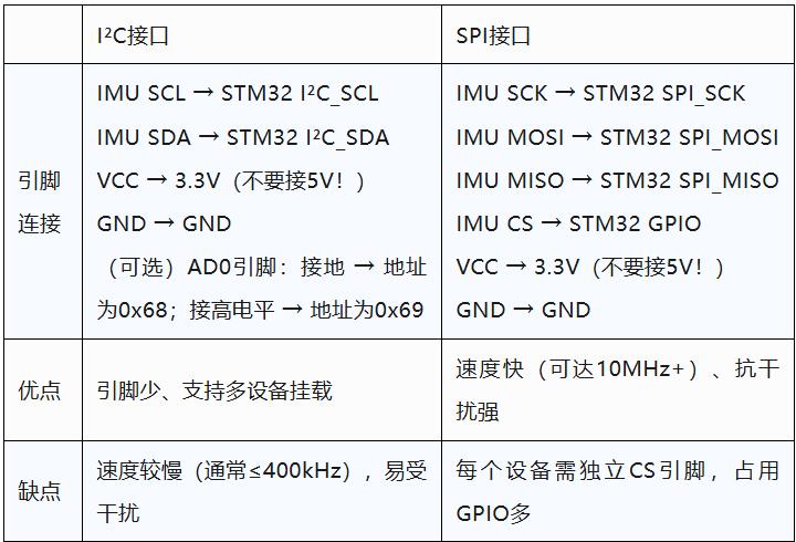
| I2C | SPI | |
|---|---|---|
| Pinout | IMU SCL to STM32 I2C_SCL, IMU SDA to STM32 I2C_SDA | IMU SCK to STM32 SPI_SCK, IMU MOSI to STM32 SPI_MOSI, IMU MISO to STM32 SPI_MISO, IMU CS to STM32 GPIO |
| Supply | VCC 3.3 V (do not use 5 V), GND to GND | VCC 3.3 V (do not use 5 V), GND to GND |
| Addressing | Optional AD0 pin: tied low gives 0x68, tied high gives 0x69 | Each device needs its own CS pin |
| Advantages | Fewer pins, supports multiple devices on one bus | Fast (10 MHz and above), noise resistant |
| Drawbacks | Slow (typically ≤400 kHz), interference prone | Consumes a GPIO per device |
A minimal HAL initialisation for I2C fast mode looks like this:
// I2C init (generated by STM32CubeMX)
hi2c1.Instance = I2C1;
hi2c1.Init.ClockSpeed = 400000; // 400 kHz fast mode
hi2c1.Init.DutyCycle = I2C_DUTYCYCLE_2;
HAL_I2C_Init(&hi2c1);
Note that I2C requires external pull-up resistors, typically 4.7 kΩ to 3.3 V, or communication will fail.
Why Manual Byte Packing Breaks Down
The traditional approach splits each int16_t into high and low bytes by hand.

That approach has three problems. It is error prone, because an off-by-one in the index silently corrupts the frame. It is hard to maintain, because adding one field forces a full re-layout. And it is inefficient, because the CPU spends its time on bit operations.
Zero-Copy Struct Packing
The core idea is to make the struct’s memory layout identical to the byte stream the UART will send.
Step 1: define the protocol struct, one-byte aligned.
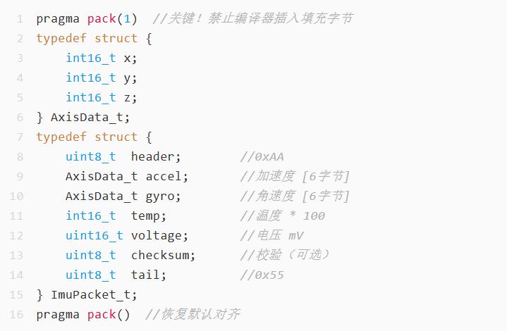
Total struct size is 1 + 6 + 6 + 2 + 2 + 1 + 1 = 19 bytes.
Step 2: use a union for zero-copy conversion.

The union’s data and buffer share the same memory, so writing data is writing buffer.
Step 3: send.
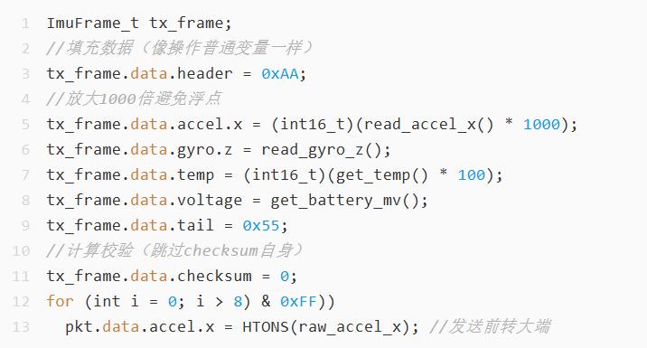
The trap: forgetting to disable struct padding. The consequence is that the actual packet length differs from the expected one, and the receiver parses everything out of alignment. Enforce it at compile time:
static_assert(sizeof(ImuPacket_t)==19, "Packet size mismatch!");Four Optimisations Worth Adding
1. Add a protocol version byte.
uint8_t version; // keeps old firmware compatible2. Use CRC16 instead of an XOR checksum.
uint16_t crc = CalcCRC16(tx_frame.buffer, sizeof(tx_frame)-2);
// store in the last two bytes (mind the endianness)
3. Wrap it in a modular function.
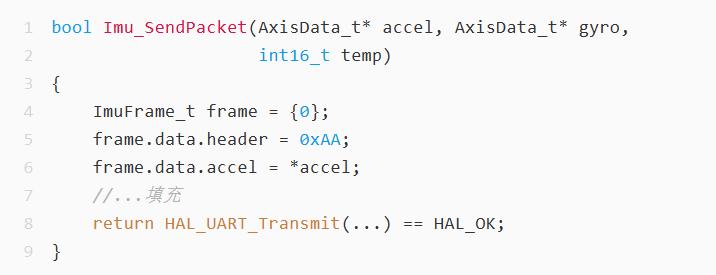
4. Mirror the struct definition on the host. In C# or C++, copy the struct definition directly. In Python, parse with struct.unpack('<B6h2HBB', data), where < means little-endian.
Traditional Packing vs Struct Plus Union
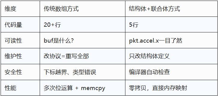
| Dimension | Traditional array packing | Struct plus union |
|---|---|---|
| Code volume | 20+ lines | 5 lines |
| Readability | What is buf[13]? |
pkt.accel.x is self-explanatory |
| Maintainability | Changing the protocol means rewriting everything | Only the struct definition changes |
| Safety | Out-of-bounds and type errors are silent | The compiler catches mismatches automatically |
| Performance | Repeated bit operations plus memcpy |
Zero copy, direct memory mapping |
Struct packing is protocol-as-code and code-as-protocol. With #pragma pack(1) plus a union, the sender packs by assignment, the receiver parses on arrival, and the whole chain is type-safe, zero-copy and readable. The technique is not limited to IMUs: it applies equally to motor control commands, sensor fusion payloads, bootloader update images and multi-vehicle coordination links. In the embedded world, memory layout is the protocol.
Have questions about this article? Feel free to contact us at [email protected] — we’re happy to help!
Frequently Asked Questions
What sample rate does a drone IMU need?
Above 1 kHz. Sampling gyro angular rate, accelerometer acceleration and magnetometer field at that rate is what lets the loop catch the small vibrations that precede a real attitude change, rather than reacting after the airframe has already moved.
Why does my drone drift even with a good IMU?
Because gyro bias integrates over time. Each flight adds a small attitude error, so the aircraft slowly wanders. Fix it with pre-flight level and compass calibration, and with GPS or BeiDou fusion on longer flights.
Should I use six-axis or nine-axis for FPV?
Six-axis for most FPV builds and consumer camera drones, where the accelerometer and gyro are enough for stable flight at lower cost. Nine-axis only when stable heading over distance matters, such as surveying or long-endurance aircraft.
I2C or SPI for connecting an IMU to an STM32?
I2C if pin count matters and 400 kHz is enough, remembering the 4.7 kΩ pull-ups to 3.3 V. SPI if you need 10 MHz or more and better noise immunity, accepting one chip-select GPIO per device.
Why does my IMU packet arrive misaligned?
Almost always struct padding. Without #pragma pack(1) the compiler inserts padding bytes, so the transmitted length no longer matches the receiver’s expectation. Guard it with static_assert on sizeof.
About Aomway
Aomway has been developing and manufacturing video transmission and UAV radio hardware for over 15 years, producing equipment for any frequency band from 1 GHz to 9 GHz at power levels from 3W to 15W. We build high-power FPV video transmitters, directional and circularly polarised antennas, digital links, fiber-optic tether systems and detection hardware for pilots, integrators and commercial operators worldwide.