
Key Takeaways
- Three independent mechanisms stack up in video stabilization: OIS works inside one frame, EIS works between frames, and rolling shutter correction works row by row within a frame.
- Each layer solves a problem the previous layer cannot. OIS prevents exposure blur; it does nothing about frame-to-frame jitter. EIS aligns frames; it cannot fix blur already baked into a single exposure.
- Gyroscopes sample at 400–800Hz and integration drifts, so a fixed rotation and time offset between gyro and camera must be calibrated, otherwise the correction is applied in the wrong direction.
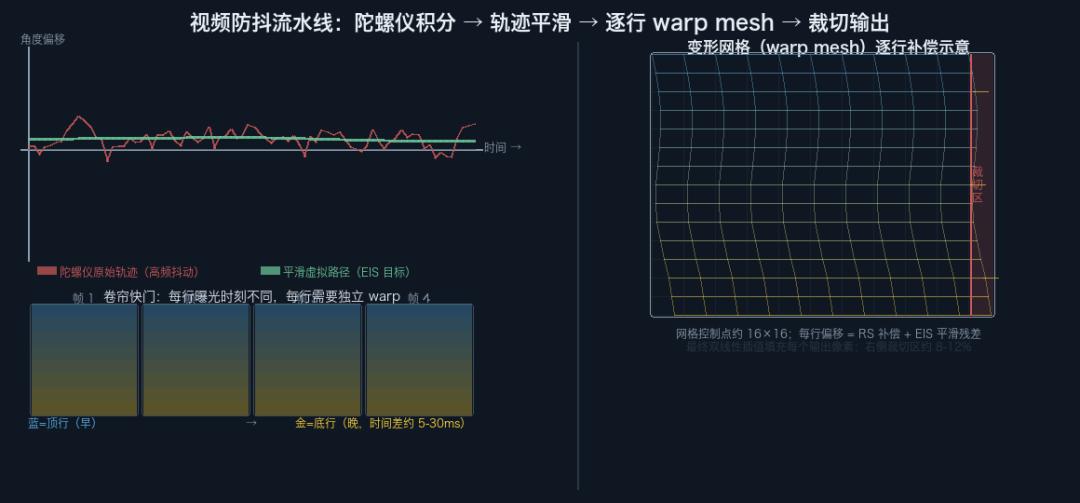
- Most phone CMOS sensors expose row by row over several milliseconds, so a correct EIS cannot apply one global transform — it needs a per-row warp, usually a coarse 16×16 mesh interpolated in hardware.
- Smoothing is a trade-off: the more aggressive the virtual path, the more crop margin you lose from the effective field of view.
You walk while recording on your phone, then play it back and the footage glides like it was on a rail. That is not one feature doing the work. At least three separate mechanisms are stacked together, and the useful way to understand video stabilization is to take them apart and see which failure each one is responsible for.
OIS and EIS Solve Two Different Problems
Start with the boundary.
OIS (optical image stabilization) works inside a single frame. Its job is to hold the optical path steady during the few milliseconds the shutter is open and the sensor is exposing, so that motion blur never forms. It does this by physically displacing a lens group or the sensor itself to cancel the angular velocity caused by hand shake. Once the shutter closes and the frame is already formed, OIS is finished.
EIS (electronic image stabilization) works between frames. Its job is to align a run of consecutive frames onto one smooth virtual camera path, removing the jitter that shows up as jumps from frame to frame. It never touches exposure. By the time EIS sees an image, that image is already formed.
Both mechanisms address the same hand-shake problem at different time scales. OIS fights intra-frame blur; EIS fights inter-frame bounce. Low light needs both, because exposures get long (making OIS more important) and multi-frame stacking demands frame-to-frame alignment (making EIS more important).
EIS Core: Integrating the Gyroscope Trace
How does EIS know the camera is moving? The most reliable answer is the gyroscope.
A gyroscope measures angular velocity about three axes at a very high rate, typically 400–800Hz. Integrating angular velocity over time yields a rotation estimate for every moment. Converting the pose difference between two frames into a transform on the image plane gives the amount of motion that frame needs to be compensated for.
There is a subtlety here. A gyroscope measures angular velocity, and integration accumulates error, which shows up as drift. On top of that, a fixed spatial rotation and a time offset exist between the gyro and the camera, and both must be calibrated at the factory or during initialization. The time offset is usually only a few milliseconds, but without that calibration the trajectory estimate is systematically biased and the correction gets applied in the wrong direction.
It gets harder when OIS is running at the same time. OIS has already physically cancelled part of the shake, so the sensor sees a partially compensated image. If EIS then estimates inter-frame motion directly from raw gyro data, it will over-correct. A joint OIS and EIS design therefore has to coordinate the two: either OIS feeds its compensation amount back to EIS, or EIS re-estimates the residual motion from optical flow on the image itself.
Rolling Shutter: Every Row Has Its Own Timestamp
This is where a phone-specific complication enters: the rolling shutter.
Most phone CMOS sensors do not expose the whole frame at one instant. They scan from the top row to the bottom row, with each row starting a few microseconds to a few tens of microseconds after the one above it. A full frame takes a few milliseconds to scan.
For a static scene this does not matter. But the moment the camera rotates during the exposure, different rows correspond to different camera poses, and a static vertical line in the world becomes a slanted line in the image. That is the classic jello effect.
A correct EIS cannot apply one uniform transform to the whole frame. It has to apply a different transform to every row, matching the camera pose at that row’s exposure instant. That requires three things:
- The gyroscope must keep sampling at high rate within the frame, not just deliver one average value per frame.
- The exposure start time of each row must be known precisely.
- The two must be mapped together so that independent affine parameters can be computed per row.
Those per-row transforms ultimately produce a warp mesh, usually at coarse resolution such as 16×16 control points, which is then interpolated in blocks across the full frame and executed efficiently in hardware.
Smoothing: Separating Shake from Intent
Gyro data tells you how the camera actually moved. That is not the same as wanting to cancel all of it.
When a user pans across a scene, that is an intentional motion and EIS should not fight it. The high-frequency tremor of walking while holding the phone is shake, and EIS should remove it. Both live in the same stretch of gyro data and must be separated.
The standard approach is trajectory smoothing: run the raw camera trajectory through a low-pass filter — a Gaussian filter or L1-optimal smoothing, for example — to obtain a virtual camera path, then align each frame to the virtual path instead of the real one. The virtual path preserves slow intentional motion and rejects high-frequency shake.
This costs something. There is an offset between the real camera motion and the virtual path, so the effective field of view in the final image is slightly smaller than the sensor resolution. You have to reserve a margin ring as compensation headroom, which is what people mean by cropping. The more aggressive the EIS, the more crop you lose. That is why stabilized video usually looks a little tighter than unstabilized video.
Why a Gyroscope Alone Is Not Enough: Optical Flow Fusion
The gyroscope’s limitation is that it only senses rotation. It cannot see pure translation. Image displacement caused by the camera moving sideways is completely invisible to a gyro.
Modern video stabilization usually adds optical flow estimation as a complement, tracking feature points or a dense flow field between frames to estimate actual image motion including the translational component. Optical flow has its own costs: heavy computation, vulnerability to contamination from moving objects, and latency.
In practice, the gyro handles high-rate, low-latency rotation estimation, while optical flow corrects low-frequency drift and supplies the translational component. Fusing the two yields a more robust motion model. Google’s ARCore EIS and SensorFlow, presented at WACV in recent years, both follow this pattern.
OIS vs EIS at a Glance
| Aspect | OIS (optical) | EIS (electronic) |
|---|---|---|
| Works within | One frame, during exposure | Between frames |
| Goal | Prevent motion blur | Align frames onto a smooth virtual path |
| Method | Physically shifts the lens group or sensor | Warps the image, per row when needed |
| Handles translation | Not really | Yes, with optical flow |
| Cost | No crop | Crop margin; more aggressive means more crop |
References
Karpenko et al., “Digital Video Stabilization and Rolling Shutter Correction using Gyroscopes,” Stanford CTSR 2011; Google Developers, “Smooth camera preview with Electronic Image Stabilization (EIS)”; Yu et al., “SensorFlow: Sensor and Image Fused Video Stabilization,” WACV 2025; the Gyroflow open-source stabilization project.
FAQ
What is the difference between OIS and EIS?
OIS stabilizes inside a single frame by physically moving a lens group or the sensor during exposure, which prevents motion blur. EIS stabilizes between frames by warping already-captured images onto a smooth virtual path. OIS fights blur; EIS fights jitter.
Why does video stabilization crop the image?
Aligning frames to a smoothed virtual path means the real camera and the virtual camera are offset, so part of the sensor image falls outside the frame. That margin becomes compensation headroom. The more aggressive the smoothing, the wider the margin and the tighter the effective field of view.
Why does EIS need the gyroscope instead of just analyzing the image?
A gyroscope measures rotation at 400–800Hz, which is fast, low-latency and unaffected by moving objects in the scene. Image-based estimation alone is slower, computationally heavier and easily confused by dynamic content, so gyro data anchors the high-frequency part of the correction.
What is the jello effect and how is it corrected?
Rolling shutter sensors expose row by row over a few milliseconds, so if the camera rotates during exposure each row sees a slightly different pose and straight lines bend. Correction requires a per-row transform derived from high-rate gyro samples and known per-row exposure times, typically baked into a coarse warp mesh.
Can gyro-only stabilization handle walking motion?
Only partially. A gyroscope senses rotation but not pure translation, and walking produces both. That is why modern systems fuse optical flow with gyro data: the gyro covers high-rate rotation while flow supplies the translational component and corrects low-frequency drift.
About Aomway
Aomway has spent more than 15 years building video transmission, antenna and camera hardware for FPV and industrial UAV teams. Explore Aomway video transmitters, antennas and optical fiber systems for long-range and interference-heavy missions.
Have questions about this article? Feel free to contact us at [email protected] — we’re happy to help!