
Key Takeaways
- A flying wing — also called a blended wing body (BWB) — buries the payload inside one large lifting surface, cutting wetted area and raising lift-to-drag ratio, while removing the vertical tail sharply reduces all-aspect radar cross section.
- The layout was shelved for decades because of poor stability and controllability, then revived in the 1990s when digital flight control matured and the B-2 entered service.
- Two structural weaknesses remain: weak longitudinal and directional stability that complicates control-law design, and a thick inboard section that limits critical Mach number for large transports.
- Flying wing airfoil design falls into three families: classic 2D airfoil design, section optimization directly in the 3D layout, and hybrid 2D-plus-3D design that uses the 2D result as the starting point for 3D refinement.
- Classic 2D design is fast but ignores spanwise crossflow. 3D optimization matches local flow better but is computationally heavy, and gradient-based methods depend heavily on the initial guess.
Source: “Progress in Airfoil Series Design for Flying Wing Configurations” by Zhang Wei, Zhao Ke, Xia Lu and Gao Zhenghong, Acta Aerodynamica Sinica, Vol. 39, No. 6, December 2021.
A flying wing is a tailless layout whose flattened shape makes the junction between fuselage and wing almost impossible to identify — the whole aircraft reads as one enormous wing. It is also called a full-wing layout or a blended wing body (BWB). Because a flying wing delivers higher aerodynamic efficiency, it is one of the layouts that can meet extreme endurance, very high altitude and low observability requirements at the same time.
There is no barrel-shaped fuselage. The payload volume sits entirely inside the large wing, so the outer shape can be designed purely around aerodynamic optimum, and the entire body becomes a lifting surface. Removing the horizontal and vertical tails eliminates protruding parts, which cuts wetted area, reduces drag and raises lift-to-drag ratio. Removing the vertical tail also removes the obvious lateral-directional control surface: with the same payload volume and a highly integrated body, all-aspect radar cross section (RCS) drops substantially, and radar stealth ends up markedly better than a conventional airframe. On both aerodynamic efficiency and stealth, the flying wing has an advantage conventional layouts cannot match.
Why the Layout Was Abandoned, Then Revived
In early research, aerodynamics and aircraft design theory were not mature enough, and the layout exposed its congenital weakness: stability and controllability were far worse than conventional aircraft. With insufficient stability, difficult handling and flight control systems that could not be certified, designers had to set the layout aside.
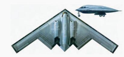
From the 1960s into the 1970s, rapid progress in electronics put computer-based control into wide use and flight control systems advanced substantially, clearing the obstacle. In the 1990s the successful development of the B-2 stealth bomber [1-2] made the flying wing a research focus again. The B-2 demonstrated the advantages clearly: payload comparable to the B-52, an unrefueled range of 12,000 km, and a radar cross section roughly 1% that of aircraft of similar size. After that, institutions in many countries began practical research, and beyond bombers the work concentrated on two areas — transports and unmanned aircraft.
Transports and Demonstrators
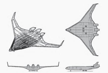
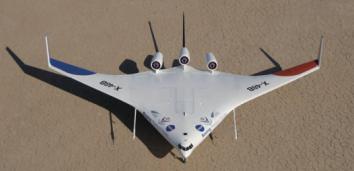
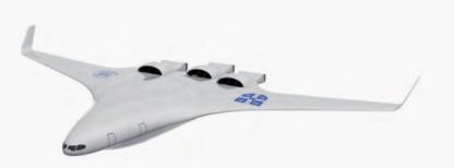
In the 1990s Boeing proposed a 450-seat flying wing transport, the BWB-450 (Figure 2), and in 2004 worked with NASA on the X-48 series demonstrators (Figure 3) to study stability and handling of the layout [2-3]. In the same period the EU ran several flying wing transport projects including MOB and VELA [4-7]. In 2003 the University of Cambridge, with MIT and other teams, began the Silent Aircraft Initiative (SAX), whose best-known output is SAX-40 [8-18], shown in Figure 4. Russia’s Central Aerohydrodynamic Institute (TsAGI) proposed a 750-seat hybrid flying wing airliner combining flying wing efficiency with conventional fuselage structure [19]. In China, Northwestern Polytechnical University, Beihang University and Nanjing University of Aeronautics and Astronautics have all continued conceptual design work on flying wing airliners [20-24].
Unmanned Aircraft: The Current Wave
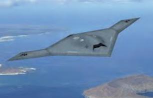
Reconnaissance and strike UAVs are a new development trend. The United States has completed several flying wing unmanned combat air vehicles, including the X-47B (Figure 5) [25], the X-45C [26-27] and the RQ-180. China has also flight-tested the Sharp Sword (Lijian). Russia’s Skat, France’s nEUROn and the UK’s Taranis all adopted the flying wing layout without exception. The flying wing UAV is clearly an important direction for future unmanned aircraft.
Two Weaknesses That Remain
1) Inherently weak longitudinal and directional stability, with complex control surface arrangements. The longitudinal scale is relatively short, which makes it hard to improve the effectiveness of longitudinal control surfaces. Generating the forces and moments a flying wing needs relies on multiple control surfaces plus thrust vectoring working together, which makes control law design difficult.
2) Unsatisfactory cruise lift-to-drag characteristics for large flying wings. Payload requirements rest almost entirely on the inboard wing region, so that region ends up with a relatively thick section, which limits cruise speed. Once cruise speed exceeds the critical Mach number, wave drag across the whole airframe rises sharply and lift-to-drag performance degrades badly. Raising the critical Mach number is therefore especially important.
Three Ways to Design a Flying Wing Airfoil
The airfoil is one of the key levers for improving flying wing performance, and research on flying wing airfoils is extensive. By design model it splits into three categories: classic airfoil design, airfoil section design in the 3D layout environment, and combined 2D/3D airfoil design.
| Approach | Design space | Strength | Weakness |
|---|---|---|---|
| Classic 2D airfoil | 2D section, with the 3D flight condition mapped down using empirical formulas | Fast; produces good sections quickly | Ignores spanwise crossflow, so 3D results disappoint |
| 3D section optimization | Directly on the 3D layout at each spanwise station | Follows local flow, better targeted performance | Very high CFD cost; gradient methods depend on the initial guess and cannot guarantee a global optimum |
| Combined 2D + 3D | 2D result used as the initial value for 3D refinement | Partially closes the gaps in both | Still bounded by the cost of the 3D stage |
1. Classic airfoil design
Classic airfoil design treats the spanwise section as a 2D problem. The design first takes the wing’s design flight condition and uses empirical formulas to map the 3D design state down to a 2D one. Liebeck et al. [3] specified an ideal velocity distribution for a subsonic airfoil and then designed the BWB-450 inboard section, arriving at the cambered-trailing-edge LW109A airfoil. Zhang Binqian et al. [28] performed multidisciplinary aerodynamic and stealth design of inboard and outboard sections and analyzed the relationship between the two disciplines. Li Quan et al. [29] studied supercritical airfoil design for flying wings. Huang Jiangtao et al. [30] applied PCA-based objective dimension reduction to multidisciplinary flying wing airfoil optimization.
Classic optimization yields airfoils with good characteristics quickly. But because spanwise crossflow effects are not considered, the results rarely perform as hoped in a 3D layout. Multidisciplinary design that must account for aerodynamics, stealth and control also places much higher demands on the design space in both dimension and scale, which increases difficulty and reduces how much the airfoil actually improves wing performance.
2. Airfoil section design in the 3D layout environment
This approach optimizes airfoil sections directly on the 3D layout. Pambagjo et al. [31] started from a NASA supercritical airfoil and used a residual-correction method based on the small-perturbation velocity potential equation to design inboard sections at several stations, producing airfoils with classic supercritical features. Peigin et al. [32] used the MOB layout and a surrogate-model global optimization method to design sections in a 3D environment, at both single-point and multi-point conditions. Hileman et al. [33] combined inboard and outboard requirements and used the MSES code for inverse design of silent aircraft airfoils. Li Peifeng et al. [34] applied the direct iterative surface curvature (DISC) method to outboard section design on a large flying wing airliner to weaken outboard shock drag. Kuntawala et al. [35] used a spline-based FFD method with adjoint gradients for multi-section aerodynamic design on a flying wing. Zingg et al. [36] used gradient algorithms to design section shape and twist. Zhou Lin et al. [37] built an adjoint-based aerodynamic and stealth co-optimization and applied it to an X-47B-like layout, co-designing sections at several spanwise stations. Kanazaki et al. [38] used an EGO method for airfoil design on a low-aspect-ratio flying wing airliner. Thomas et al. [39] compared airfoil designs for wide-body and narrow-body flying wing airliners and compared their aerodynamic and fuel efficiency. Martins et al. [40] designed a flying wing airliner accounting for aerodynamics, trim and handling, optimizing sections at three stations.
Designing sections in the 3D environment follows local flow conditions more faithfully and yields better-performing airfoils for a given requirement. The direct problem is cost: 3D physical models are expensive to compute, multidisciplinary optimization multiplies that, computational resources become the binding constraint, and global optimization over a wide design space is even harder. Adjoint gradient methods raise efficiency substantially, but gradient algorithms are local searches by nature, so results depend heavily on the quality of the initial model and convergence to a global optimum is not guaranteed.
3. Combined 2D and 3D airfoil design
To address those problems, Qin et al. [7] used a gradient optimization approach in two stages: first design the airfoil with the classic 2D model, then take that result as the initial value for refined section design in the 3D flying wing layout. Combining 2D and 3D conditions this way partially offsets the shortcomings of pure classic design and pure 3D section optimization.
References
[1] Lu Chengwen, ed. World Aircraft Handbook [M]. Beijing: Aviation Industry Press, 1994.
[2] GRIFFIN J M, KINNU J K, COLOMBI J M. B-2 systems engineering case study[R]. Defense Technical Information Center, 2007. ADA 464771. doi:10.21236/ada464771
[3] LIEBECK R, PAGE M, RAWDON B. Blended-wing-body subsonic commercial transport[C]//36th AIAA Aerospace Sciences Meeting and Exhibit, Reno, NV, USA. Reston, Virginia: AIAA, 1998. AIAA-98-0438. doi:10.2514/6.1998-438
[4] MORRIS A, MOB A. European distributed multi-disciplinary design and optimisation project[C]//9th AIAA/ISSMO Symposium on Multidisciplinary Analysis and Optimization, Atlanta, Georgia. Reston, Virginia: AIAA, 2002. AIAA 2002-5444. doi:10.2514/6.2002-5444
[5] LABAN M, ARENDSEN P, ROUWHORST W, et al. A computational design engine for multi-disciplinary optimisation with application to a blended wing body configuration[C]//9th AIAA/ISSMO Symposium on Multidisciplinary Analysis and Optimization, Atlanta, Georgia. Reston, Virginia: AIAA, 2002. AIAA 2002-5446. doi:10.2514/6.2002-5446
[6] LA ROCCA G, KRAKERS L, VAN TOOREN M. Development of an ICAD generative model for blended wing-body aircraft design[C]//9th AIAA/ISSMO Symposium on Multidisciplinary Analysis and Optimization, Atlanta, Georgia. Reston, Virginia: AIAA, 2002. AIAA 2002-5447. doi:10.2514/6.2002-5447
[7] QIN N. Aerodynamic studies for blended wing body aircraft[C]//9th AIAA/ISSMO Symposium on Multidisciplinary Analysis and Optimization, Atlanta, Georgia. Reston, Virginia: AIAA, 2002. AIAA 2002-5448. doi:10.2514/6.2002-5448
[8] HILEMAN J, SPAKOVSZKY Z, DRELA M, et al. Aerodynamic and aeroacoustic three-dimensional design for a “silent” aircraft[C]//44th AIAA Aerospace Sciences Meeting and Exhibit, Reno, Nevada. Reston, Virginia: AIAA, 2006. AIAA 2006-241. doi:10.2514/6.2006-241
[9] MANNEVILLE A, PILCZER D, SPAKOVSZKY Z S. Preliminary evaluation of noise reduction approaches for a functionally silent aircraft[J]. Journal of Aircraft, 2006, 43(3): 836−840. doi:10.2514/1.16424
[10] HILEMAN J, REYNOLDS T, DE LA ROSA BLANCO E, et al. Development of approach procedures for silent aircraft[C]//45th AIAA Aerospace Sciences Meeting and Exhibit, Reno, Nevada. Reston, Virginia: AIAA, 2007. AIAA 2007-451. doi:10.2514/6.2007-451
[11] DIEDRICH A, HILEMAN J, TAN D, et al. Multidisciplinary design and optimization of the silent aircraft[C]//44th AIAA Aerospace Sciences Meeting and Exhibit, Reno, Nevada. Reston, Virginia: AIAA, 2006. AIAA 2006-1323. doi:10.2514/6.2006-1323
[12] HALL C A, CRICHTON D. Engine and installation configurations for a silent aircraft[R]. ISABE 2005-1164.
[13] HALL C A, CRICHTON D. Engine design studies for a silent aircraft[J]. Journal of Turbomachinery, 2007, 129(3): 479−487. doi:10.1115/1.2472398
[14] DE LA ROSA BLANCO E, HALL C, CRICHTON D. Challenges in the silent aircraft engine design[C]//45th AIAA Aerospace Sciences Meeting and Exhibit, Reno, Nevada. Reston, Virginia: AIAA, 2007. AIAA 2007-454. doi:10.2514/6.2007-454
[15] HILEMAN J, SPAKOVSZKY Z, DRELA M, et al. Airframe design for “silent aircraft”[C]//45th AIAA Aerospace Sciences Meeting and Exhibit, Reno, Nevada. Reston, Virginia: AIAA, 2007. AIAA 2007-453. doi:10.2514/6.2007-453
[16] MODY P, SATO S, HALL D, et al. Conceptual design of an N+3 hybrid wing body subsonic transport[C]//28th AIAA Applied Aerodynamics Conference, Chicago, Illinois. Reston, Virginia: AIAA, 2010. AIAA 2010-4812. doi:10.2514/6.2010-4812
[17] KIM H J, LIOU M S. Optimal inlet shape design of N2B hybrid wing body configuration[C]//48th AIAA/ASME/SAE/ASEE Joint Propulsion Conference & Exhibit, Atlanta, Georgia. Reston, Virginia: AIAA, 2012. AIAA 2012-3917. doi:10.2514/6.2012-3917
[18] KIM H, LIOU M S. Optimal shape design of mail-slot nacelle on N3-X hybrid wing body configuration[C]//31st AIAA Applied Aerodynamics Conference, San Diego, CA. Reston, Virginia: AIAA, 2013. AIAA 2013-2413. doi:10.2514/6.2013-2413
[19] DENISOV V, SHKADOV L, CHERNYSHEV S. The flying wing concept — the challenge for the future[C]//AIAA International Air and Space Symposium and Exposition: The Next 100 Years, Dayton, Ohio. Reston, Virginia: AIAA, 2003. AIAA 2003-2887. doi:10.2514/6.2003-2887
[20] Yang Yufei, Bai Junqiang, Xia Lu. Aerodynamic design of flying wing transport[J]. Aeronautical Computing Technique, 2007, 37(1): 22-26 (in Chinese).
[21] Song Qian, Wan Zhiqiang. Aerodynamic/structural integrated design for the wing of flying wing airliner[J]. Civil Aircraft Design & Research, 2018(4): 6−14 (in Chinese).
[22] Suo Xinshi. Integrated analysis, evaluation and optimization in conceptual design of blended wing body commercial aircraft[D]. Nanjing: Nanjing University of Aeronautics and Astronautics, 2017 (in Chinese).
[23] Liu Xiaojing, Wu Jianghao, Zhang Shuguang. Aerodynamic design and optimization of the blended wing body aircraft for 250 passengers[J]. Acta Aerodynamica Sinica, 2011, 29(1): 78−84 (in Chinese). doi:10.3969/j.issn.0258-1825.2011.01.013
[24] Chai Xiao, Chen Yingchun, Tan Zhaoguang, et al. Analysis and optimization of overall parameters for blended-wing-body civil aircraft[J]. Acta Aeronautica et Astronautica Sinica, 2019, 40(9): 623042 (in Chinese).
[25] WHITTENBURY J. Configuration design development of the navy UCAS-D X-47B[C]//AIAA Centennial of Naval Aviation Forum, Virginia Beach, VA. Reston, Virginia: AIAA, 2011. AIAA 2011-7041. doi:10.2514/6.2011-7041
[26] CHAPMAN II COL R E. Unmanned combat aerial vehicles: Dawn of a new age?[J] Aerospace Power Journal, 2002, (2): 60-73.
[27] NANGIA R, PALMER M. A comparative study of UCAV type wing planforms — aero performance & stability considerations[C]//23rd AIAA Applied Aerodynamics Conference, Toronto, Ontario, Canada. Reston, Virginia: AIAA, 2005. AIAA 2005-5078. doi:10.2514/6.2005-5078
[28] Zhang Binqian, Luo Lie, Chen Zhenli, et al. On stealth airfoil optimization design for flying wing configuration[J]. Acta Aeronautica et Astronautica Sinica, 2014, 35(4): 957−967 (in Chinese).
[29] Li Quan, Guo Zhaodian, Lei Wutao, et al. Study on supercritical airfoil of blended wing body[J]. Acta Aerodynamica Sinica, 2017, 35(4): 579−586 (in Chinese). doi:10.7638/kqdlxxb-2017.0073
[30] Zheng Chuanyu, Huang Jiangtao, Zhou Zhu, et al. Multidisciplinary optimization design of high dimensional target space for flying wing airfoil[J]. Acta Aerodynamica Sinica, 2017, 35(4): 587−597 (in Chinese). doi:10.7638/kqdlxxb-2017.0079
[31] PAMBAGJO T, NAKAHASHI K, OBAYASHI S, et al. Aerodynamic design of a medium size blended-wing-body airplane[C]//39th Aerospace Sciences Meeting and Exhibit, Reno, NV, USA. Reston, Virginia: AIAA, 2001. AIAA 2001-129. doi:10.2514/6.2001-129
[32] PEIGIN S, EPSTEIN B. Computational fluid dynamics driven optimization of blended wing body aircraft[J]. AIAA Journal, 2006, 44(11): 2736−2745. doi:10.2514/1.19757
[33] HILEMAN J I, SPAKOVSZKY Z S, DRELA M, et al. Airframe design for silent fuel-efficient aircraft[J]. Journal of Aircraft, 2010, 47(3): 956−969. doi:10.2514/1.46545
[34] LI P F, ZHANG B Q, CHEN Y C, et al. Aerodynamic design methodology for blended wing body transport[J]. Chinese Journal of Aeronautics, 2012, 25(4): 508−516. doi:10.1016/s1000-9361(11)60414-7
[35] KUNTAWALA N B, HICKEN J E, ZINGG D W. Preliminary aerodynamic shape optimization of a blended-wing-body aircraft configuration[C]//49th AIAA Aerospace Sciences Meeting, Orlando, Florida. AIAA 2011-642. doi:10.2514/6.2011-642
[36] REIST T A, ZINGG D W. Aerodynamic shape optimization of a blended-wing-body regional transport for a short range mission[C]//31st AIAA Applied Aerodynamics Conference, San Diego, CA. Reston, Virginia: AIAA, 2013. doi:10.2514/6.2013-2414
[37] ZHOU L, HUANG J T, GAO Z H, et al. Three-dimensional aerodynamic/stealth optimization based on adjoint sensitivity analysis for scattering problem[J]. AIAA Journal, 2020, 58(6): 2702−2715. doi:10.2514/1.J059136
[38] KANAZAKI M, HANIDA R, NARA T, et al. Challenge of design exploration for small blended wing body using unstructured flow solver[J]. Computers & Fluids, 2013, 85: 71−77. doi:10.1016/j.compfluid.2012.09.023
[39] REIST T A, ZINGG D W. Aerodynamic design of blended wing-body and lifting-fuselage aircraft[C]//34th AIAA Applied Aerodynamics Conference, Washington, D.C. Reston, Virginia: AIAA, 2016. AIAA 2016-3874. doi:10.2514/6.2016-3874
[40] LYU Z J, MARTINS J R R A. Aerodynamic design optimization studies of a blended-wing-body aircraft[J]. Journal of Aircraft, 2014, 51(5): 1604−1617. doi:10.2514/1.C032491
FAQ
What is a flying wing or blended wing body?
A flying wing is a tailless layout with no distinct fuselage, so the whole aircraft acts as one large lifting surface. When the payload volume is blended into a thick center body it is called a blended wing body. Both trade tail volume for lower drag and lower radar signature.
Why were flying wings abandoned and then revived?
Early designs had poor stability and controllability, and flight control systems of the era could not handle them. Digital fly-by-wire matured in the 1960s and 1970s, and the B-2’s success in the 1990s proved the layout was practical, which restarted research worldwide.
What is the hardest part of flying wing airfoil design?
Reconciling a 2D section with a strongly three-dimensional flow field. Classic 2D design is fast but ignores spanwise crossflow, while 3D section optimization matches local flow but is computationally expensive and, with gradient methods, sensitive to the initial guess.
Why do large flying wings struggle at high cruise speed?
Payload volume sits almost entirely in the inboard wing, forcing a thick section there. That thickness lowers the critical Mach number, so once cruise speed passes it, wave drag rises sharply across the airframe and lift-to-drag performance falls away.
What does the combined 2D and 3D method add?
It runs classic 2D airfoil design first, then uses that result as the initial value for refined 3D section optimization. This gives the gradient optimizer a strong starting point, cutting cost while recovering much of the local-flow fidelity that pure 2D design loses.
About Aomway
Aomway has spent more than 15 years building video transmission, antenna and flight hardware for FPV and industrial UAV teams. Explore Aomway video transmitters, antennas and optical fiber systems for long-range and demanding missions.
Have questions about this article? Feel free to contact us at [email protected] — we’re happy to help!