In multi-sensor fusion experiments, many people need to synchronize LiDAR with multiple cameras. Here we demonstrate the process using several camera models:
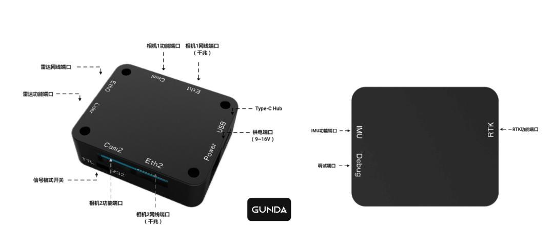
LiDAR
The synchronizer currently supports two types of LiDAR synchronization signals (TTL and RS232). Here we use the Livox Mid-360 as an example — its trigger signal type is TTL, and the GPRMC communication baud rate is 9600.
Hardware Connection
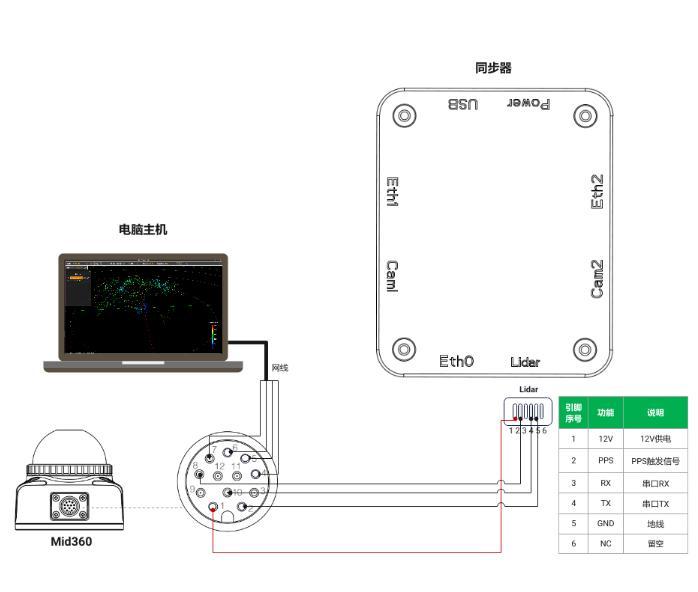
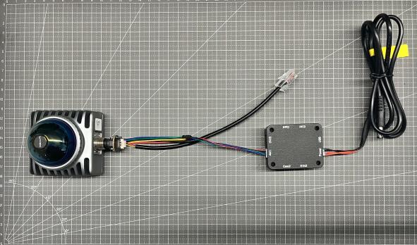
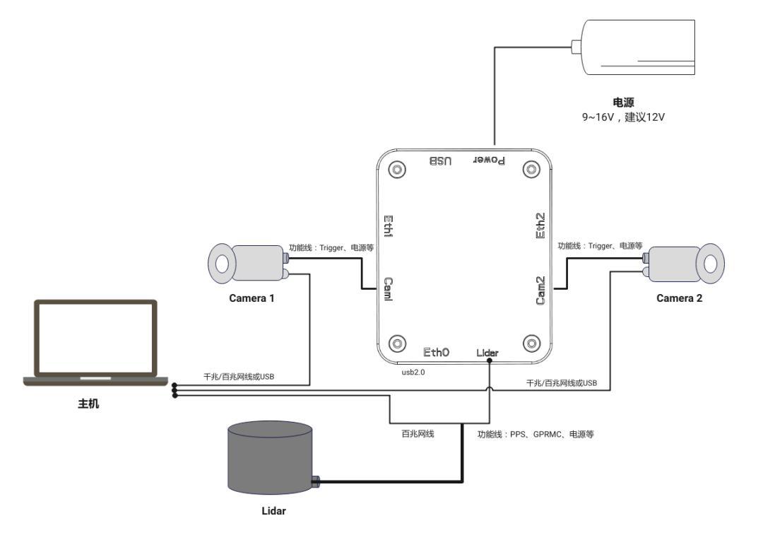
Physical connection
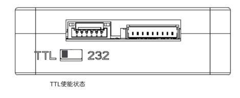
After wiring is complete, adjust and confirm the signal selector Switcher to ensure it’s in TTL enabled state, as shown below:
Software Configuration
Open the LivoxViewer2 client that comes with Mid-360 and observe the synchronization status:
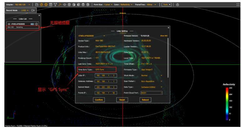
If it displays as shown above, the Mid-360 has entered synchronization state.
Cameras
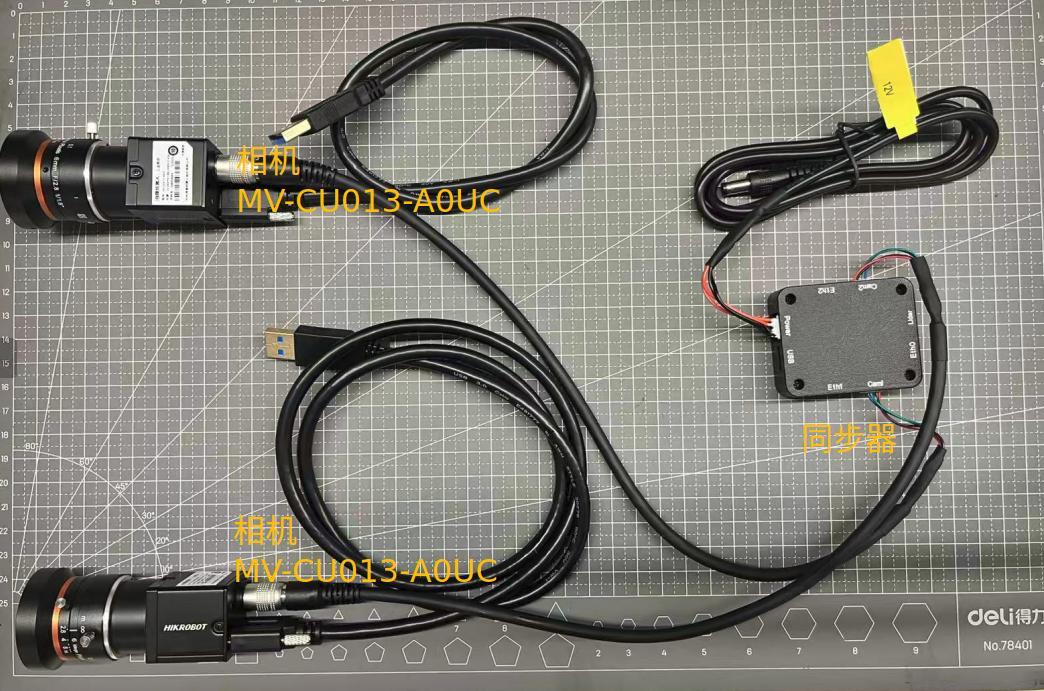
Combination 1: Two MV-CU013-A0UC
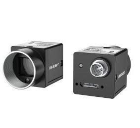
Note: The MV-CU013-A0UC is the camera model commonly used for Fast-LIVO2, which most readers should be familiar with.
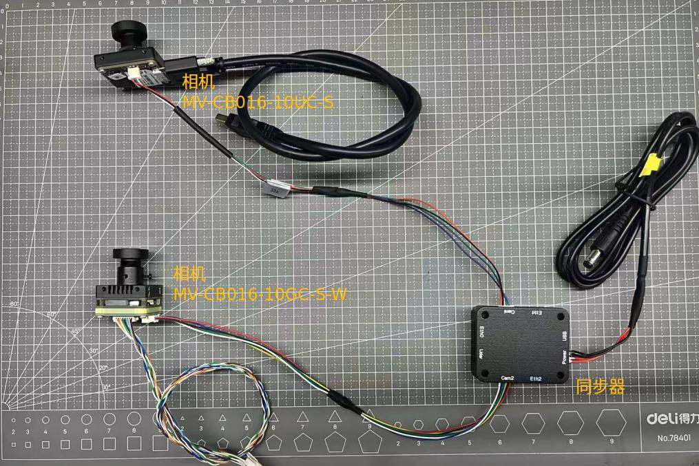
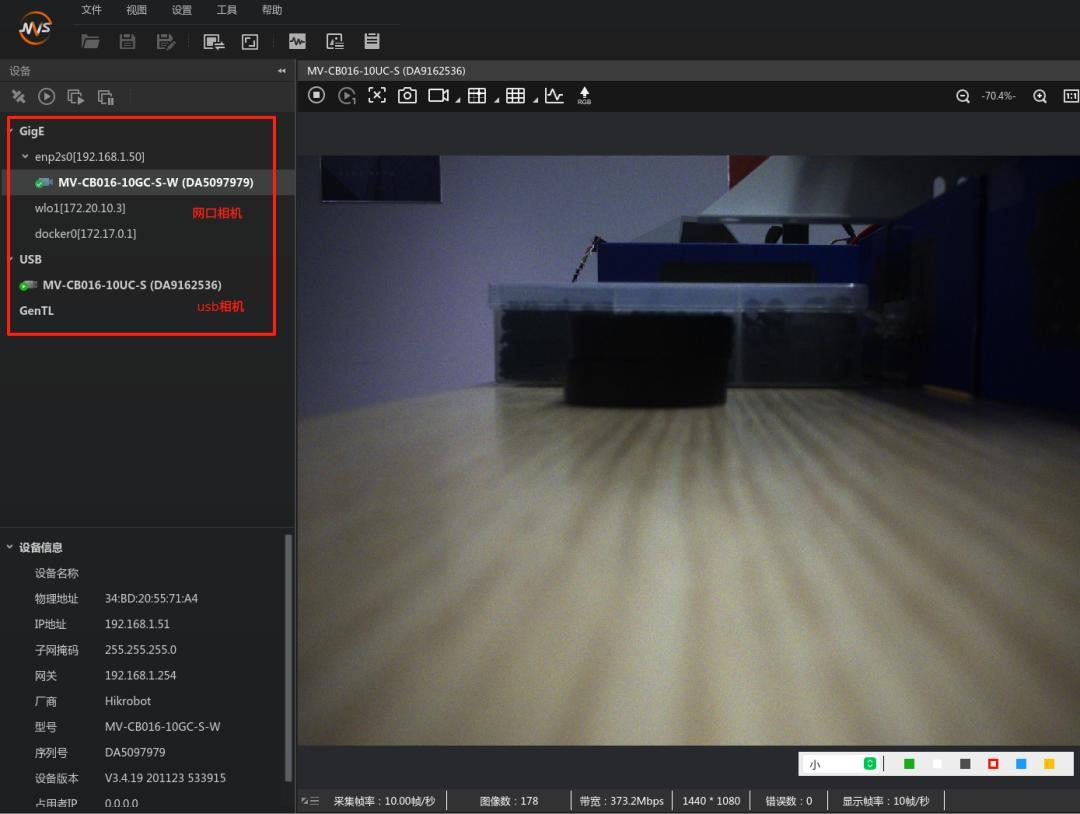
Combination 2: One MV-CB016-10UC-S + One MV-CB016-10GC-S-W
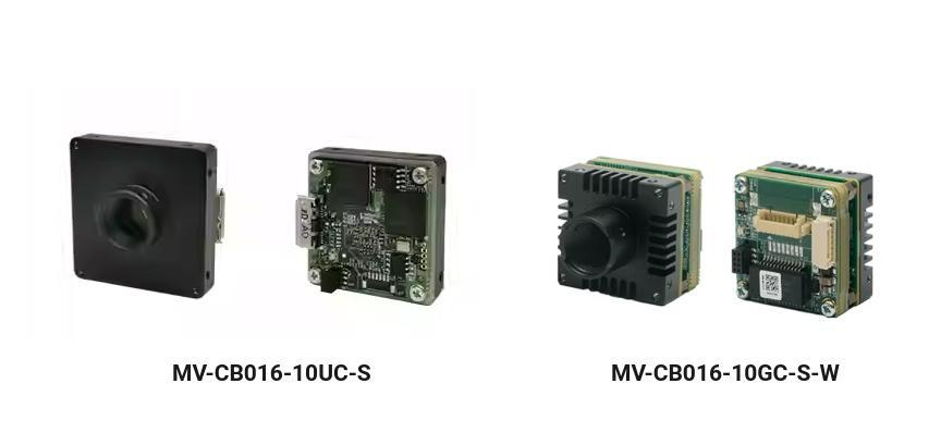
Note: Both are Hikrobot CB series USB3.0 board-level industrial cameras. The CB series features a modular board-level design — more compact and flexible for embedding into equipment or embedded systems. Resolution: 1440×1280. The MV-CB016-10UC-S uses USB communication, while the MV-CB016-10GC-S-W uses Gigabit Ethernet.
Hardware Principles
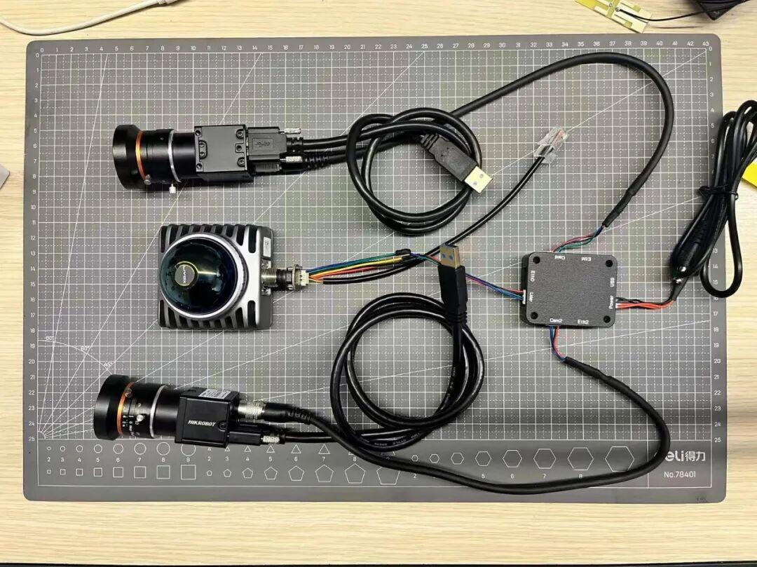
A. Combination 1 — Two MV-CU013-A0UC
Physical wiring
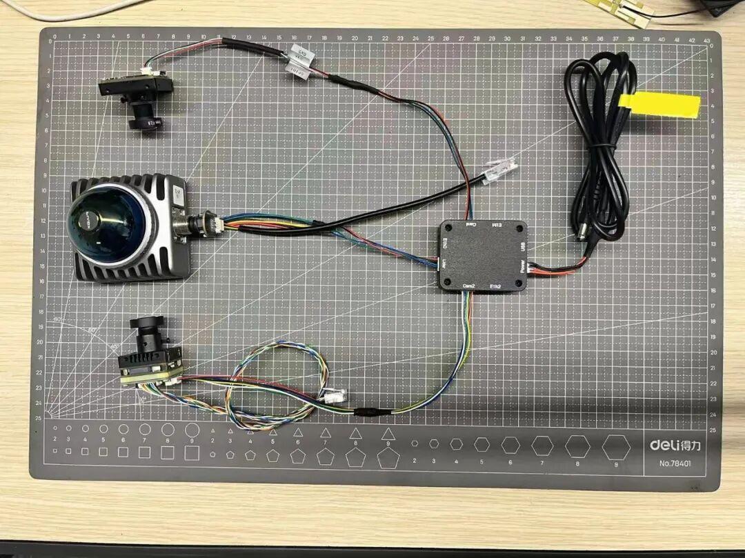
B. Combination 2 — One MV-CB016-10UC-S + One MV-CB016-10GC-S-W
Physical wiring
Verify physical connections:
Two MV-CU013-A0UC
One MV-CB016-10UC-S + One MV-CB016-10GC-S-W
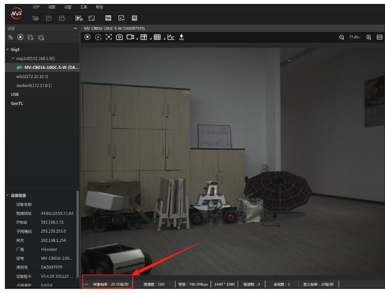
Before opening the MVS client, you need to switch the camera trigger mode. Connect the camera Ethernet cable to the host, open the MVS client, and change the trigger mode from internal trigger (default) to external trigger, as shown below:
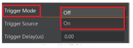
Through external triggering, verify that the synchronizer can correctly trigger the cameras.
The MV-CU013-A0UC, MV-CB016-10UC-S, and MV-CB016-10GC-S-W all follow the same procedure above.
The synchronizer defaults to a 10Hz trigger frequency. Normally, cameras can be triggered directly after plugging in — no additional operations needed. For other frequencies, modify the camera port trigger frame rate as follows:
1. Connect the debug cable to your computer, open the “Serial Assistant” client, and establish a connection.
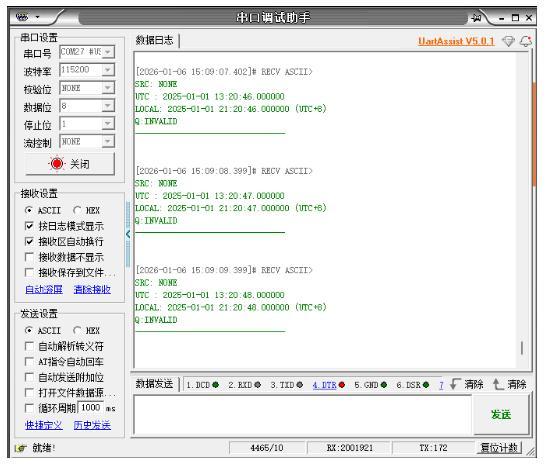
In the send window, enter $SETCAMFPS,10, then click “Send” to send the command to the synchronizer. Observe the returned data:
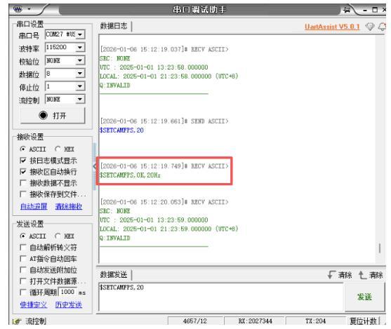
When you see the return data in the red box, the setting was successful. Restart the synchronizer for it to take effect.
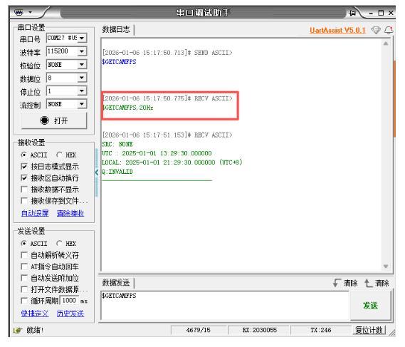
You can also enter $GETCAMFPS in the send window and click “Send” to query the current camera trigger frame rate:
You can also view the actual camera output frame rate in MVS:
Software Configuration Principles
Software environment: Ubuntu 20.04, ROS1 Noetic. The LiDAR driver uses the livox_ros_driver2 package, and the camera driver uses the mvs_ros_driver package.
Note: Both drivers have built-in “time alignment” functionality.
The LiDAR driver is straightforward — just modify the IP address in livox_ros_driver2/config/MID360_config.json. We’ll focus on the camera driver:
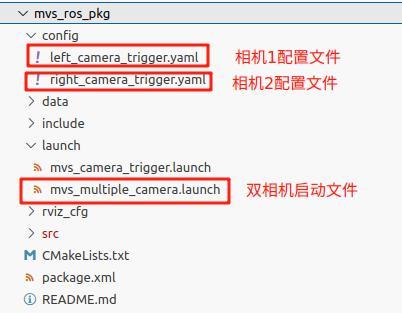
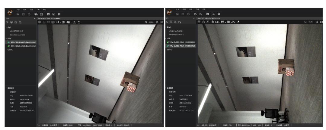
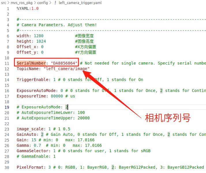
You need to check the camera serial numbers in the MVS client, then fill them into the SerialNumber parameter in left_camera_trigger.yaml and right_camera_trigger.yaml respectively.
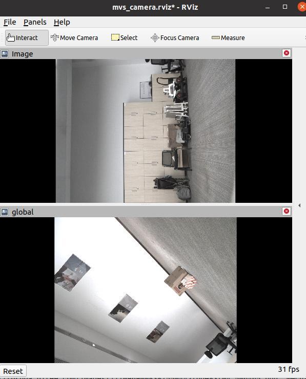
After preparation, launch the mvs_multiple_camera.launch file to view both camera images:
Combined Setup
Synchronization Verification
Here we use a script to verify frame-by-frame synchronization between LiDAR and cameras, and between cameras. In addition to comparing Header/stamp in the Topic, we also include the subscription time T from the RosBag for data link layer delay analysis:
stamp time (msg.header.stamp): verifies whether "synchronizer/timestamp injection" is consistent
bag record time (t.to_sec()): verifies jitter and latency in the "message arrival/recording/publishing" link
The script data_anaylist_mutil_cam.py performs the following analysis for each target sensor relative to a reference sensor (LiDAR):
- Extracts dual timestamps (header.stamp and bag record time) from rosbag for each topic
- Matches each target timestamp to the nearest reference timestamp
- Applies a matching window (|diff| ≤ 60ms) to filter invalid matches
- Removes spike anomalies (|diff[i] – diff[i-1]| > 50ms)
- Reports statistics: min/max/mean/std, anomalous frames, and out-of-window frames
- Generates matplotlib plots for visual inspection
Key analysis results from the test bag (110 frames per sensor, after trimming 3 head/tail frames):
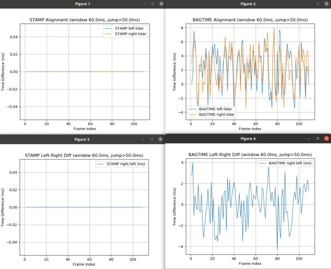
STAMP Alignment (header.stamp based)
| Pair | Valid Points | Min (ms) | Max (ms) | Mean (ms) | Std (ms) |
|---|---|---|---|---|---|
| left → lidar | 109/110 | 0.000 | 0.000 | 0.000 | 0.000 |
| right → lidar | 109/110 | 0.000 | 0.000 | 0.000 | 0.000 |
| right → left | 109/110 | 0.000 | 0.000 | 0.000 | 0.000 |
BAGTIME Alignment (bag record time based)
| Pair | Valid Points | Min (ms) | Max (ms) | Mean (ms) | Std (ms) |
|---|---|---|---|---|---|
| left → lidar | 109/110 | -4.44 | +7.96 | +2.28 | 2.90 |
| right → lidar | 109/110 | -3.49 | +7.74 | +2.30 | 2.64 |
| right → left | 109/110 | -4.35 | +3.98 | +0.02 | 1.75 |
Conclusion Analysis
Conclusion 1: Near-Perfect Synchronization Under STAMP
Under the STAMP metric, left/right cameras and LiDAR show header.stamp values that are completely identical across 109/110 frames. All metrics (min/max/mean/std) are 0ms. This confirms that the driver-level “time alignment” is working correctly and effectively.
Conclusion 2: BAGTIME Reveals Link Layer Jitter
BAGTIME shows that camera messages arrive at the bag recorder approximately 2.3ms after LiDAR messages (mean), with a standard deviation of ~2.6-2.9ms. This is not a synchronization failure — it reflects the natural jitter in the message publishing/recording pipeline. The LiDAR message tends to enter the bag slightly earlier, likely due to differences in driver publish timing and ROS scheduling.
Conclusion 3: Stereo Pair Link Stability
The BAGTIME_LR metric (right vs left camera) shows a mean of 0.022ms and std of 1.75ms — nearly zero bias between the two cameras, with ~1.75ms relative jitter. This is excellent for USB/driver/ROS scheduling environments and explains why left and right show very similar statistics relative to LiDAR: both camera links behave consistently.
For multi-sensor synchronization solutions and FAST-LIVO2 integration support, Aomway provides consulting and engineering services. Contact us at [email protected] for more information.
Frequently Asked Questions
1. What is hardware synchronization and why is it needed for LiDAR-camera systems?
Hardware synchronization ensures that multiple sensors (LiDAR, cameras) capture data at precisely the same instant, controlled by an external trigger signal rather than each sensor’s internal clock. This is critical for sensor fusion algorithms like FAST-LIVO2, where even a few milliseconds of misalignment between LiDAR scans and camera frames can cause point cloud registration errors, visual artifacting, and degraded SLAM performance. A hardware synchronizer sends trigger pulses to all sensors simultaneously, and the drivers inject consistent timestamps into the message headers — achieving the sub-millisecond alignment shown in the STAMP results above.
2. What’s the difference between TTL and RS232 trigger signals?
TTL (Transistor-Transistor Logic) signals are simple digital pulses (0V/3.3V or 0V/5V) — most common for short-range trigger connections. The Livox Mid-360 uses TTL triggering. RS232 is a serial communication standard using higher voltage levels (±12V) and is used for sensors that require serial communication for synchronization (like some older LiDAR models). The synchronizer in this article supports both types — you select the appropriate mode via the Switcher. Aomway’s integration team can help identify which signal type your specific sensor requires.
3. Why does STAMP show perfect 0ms alignment but BAGTIME shows ~2ms offset?
This is the key insight from the synchronization verification. STAMP uses header.stamp — the timestamp injected by the driver when the sensor data arrives. Since the hardware synchronizer triggers all sensors simultaneously and the driver writes the same timestamp, STAMP shows perfect alignment. BAGTIME uses the rosbag record time — when the message actually arrives at the recorder through the ROS publish/subscribe pipeline. The ~2ms offset reflects processing and transport latency in the ROS middleware: driver processing time, message serialization, topic publishing, and bag write scheduling. This is normal and expected — it’s not a synchronization error but a measurement pipeline artifact.
4. Can I use different camera models in the same synchronized setup?
Yes, as demonstrated in this article — the synchronizer can trigger different camera models simultaneously. The key requirement is that all cameras support external trigger mode and are configured to use it. The two combinations shown (two MV-CU013-A0UC units, or one MV-CB016-10UC-S + one MV-CB016-10GC-S-W) both work correctly. When mixing USB and GigE cameras, be aware that internal processing latencies may differ slightly between models, but the hardware trigger ensures capture timing alignment. The driver’s time alignment feature handles timestamp consistency. Aomway has verified multiple camera combinations for FAST-LIVO2 and similar multi-sensor fusion applications.
5. How do I change the trigger frequency from the default 10Hz?
Connect the synchronizer’s debug cable to your computer, open a serial terminal (like the Serial Assistant shown in the article), and send the command $SETCAMFPS,X where X is the desired frequency in Hz. The synchronizer will return a confirmation message. After setting, restart the synchronizer for the new frequency to take effect. You can verify the current setting by sending $GETCAMFPS. Note that the maximum trigger frequency is limited by the slowest sensor in your setup — if your camera’s maximum frame rate is 30fps, setting the synchronizer to 40Hz won’t produce valid frames for every trigger. Always check sensor specifications and verify actual output frame rates in the MVS client.
Need help with multi-sensor synchronization, FAST-LIVO2 setup, or LiDAR-camera calibration? Aomway provides hardware integration, driver configuration, and synchronization verification services. Contact us at [email protected].
