

Key Takeaways
- CG is everything — ~50% of fixed-wing crashes come from incorrect center of gravity. Always measure before every flight.
- Servo direction kills — a single reversed aileron or elevator means instant crash. Verify every control surface in Mission Planner before the first flight.
- Choose EPP foam for your first build — it is cheap ($15-25), crash-tolerant, and has generous CG tolerance for beginners.
- Airspeed is life — fixed-wings stall without enough speed. Always install and calibrate a pitot tube airspeed sensor.
- Aomway drone video transmission systems share the same reliability engineering principles covered in this build guide — every connection, every surface, every check matters.
Here is a real lesson from last autumn. A friend spent three days building his first fixed-wing aircraft. Motor rotation was correct, GPS had a fix, the transmitter was bound. He hand-launched — the plane climbed steadily — then 2 seconds later it plunged nose-first into the grass. Propeller shattered into three pieces. Fuselage frame snapped.
After 4 hours of troubleshooting, the cause was almost embarrassing: the battery was mounted too far forward, shifting the CG nearly 20mm off. Moving it back 2cm made the second flight as stable as a rail.
That single “move the battery” action cost him an entire electronics set and a weekend of confidence.
The brutal truth about fixed-wing aircraft: multirotors can hover and self-correct if something is wrong. Fixed-wings commit on takeoff — there is no second chance once airborne.
This guide covers everything learned through crashes, consultations with experienced builders, and hundreds of hours of flight testing. Seven major stages, 40+ critical details, 15 fatal errors. If it saves you one crash, it was worth writing.
1. Understand the Difference: Fixed-Wing vs Multirotor
Many pilots transitioning from multirotors think “it is just fewer motors and adding servos.” This assumption is dangerously wrong.
Multirotors stabilize through differential thrust. Fixed-wings rely on aerodynamic balance. A multirotor with an off CG compensates automatically through its flight controller adjusting four motor speeds. A fixed-wing with incorrect CG creates wrong moment arms on the wing and tail — the flight controller cannot compute its way out of a fundamental aerodynamic imbalance.
Fixed-wings have three critical differences from multirotors:
Critical Difference 1: Center of Gravity (CG) — For multirotors, CG is a “nice to center.” For fixed-wings, CG is a life-or-death parameter. Entry-level fixed-wings require CG at 25%-33% of wing chord from the leading edge at the widest point. Exact values vary by airframe — always start from the manufacturer’s recommendation.
Critical Difference 2: Control Surface Direction — Multirotors have no control surfaces. Fixed-wings have three: ailerons (roll), elevator (pitch), rudder (yaw). Three servo connections — get one wrong and the aircraft crashes.
Critical Difference 3: Airspeed — Multirotors do not need to know their speed. Fixed-wings must. Insufficient airspeed means stall, which means nose-down descent. This is why fixed-wings require an airspeed sensor.
Remember this: A multirotor assembled incorrectly can be repaired. A fixed-wing assembled incorrectly can only be buried.
2. Choosing Your First Fixed-Wing Aircraft
Bottom line upfront: choose an EPP foam trainer.
Three reasons:
- Affordable and crash-resistant — EPP foam airframes absorb impacts without shattering. Complete kit with flight controller runs approximately $80-140. A replacement foam fuselage costs under $10. 3D-printed airframes look better and perform stronger, but print times are long and crash repairs require re-printing damaged sections.
- Forgiving flight characteristics — Entry-level airframes with 1.2-1.5m wingspan and 700g-1.5kg flying weight need only 0.3x thrust-to-weight for level flight, 0.5x for hand-launch. CG tolerance is generous — 5-10mm off center is still flyable.
- Mature component ecosystem — Motor, ESC, servo, and propeller choices are well-established with documented standards.
Beginner comparison:
| Criterion | EPP Foam ARF (e.g., Sky Surfer X8) | 3D-Printed Kit (e.g., Titan Comet) |
|---|---|---|
| Assembly difficulty | Install electronics only | Print + sand + glue + carbon rods |
| Crash repair | $10 foam patch | Re-print damaged sections |
| CG tolerance | Generous (5-10mm off still flyable) | Tight (3-5mm off causes instability) |
| Budget | $80-110 | $140-280 |
Recommended beginner configuration (EPP trainer):
| Component | Model/Spec | Notes |
|---|---|---|
| Airframe | EPP foam fixed-wing (1.2-1.5m wingspan) | Sky Surfer X8 etc., ~300-500g bare |
| Motor | 2212 high-KV brushless (1400-2200KV) | Single pusher — entry standard configuration |
| ESC | 30-40A with BEC | 5V/3A BEC output for servo power |
| Servos | 9g plastic gear × 4 | Left/right aileron, elevator, rudder — one each |
| Propeller | 6-7 inch electric prop | Use the largest size that fits the motor mount |
| Battery | 3S 2200-3000mAh 25C | Approximately 15-25 minutes flight time |
| Flight Controller | Pixhawk 2.4.8 or Matek F405-WING | Flash with ArduPlane firmware |
| Transmitter | FS-i6X / RadioMaster Zorro | 6+ channels, $28-55 |

Pitfalls for beginners:
- Do not start with a 2m wingspan FPV platform — learn fundamentals on a 1.2-1.5m trainer first
- Do not modify thrust angles or swap propellers early — factory configuration flies, get airborne first
- Do not undersize the battery — 1500mAh gives under 10 minutes; 2200mAh is the practical minimum — Aomway battery straps with anti-slip padding help keep CG consistent during flight
3. Assembly: From Parts to Complete Airframe
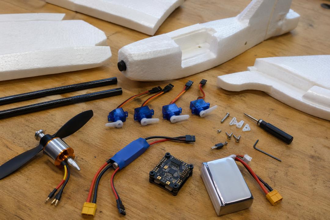
Required tools: PH2 cross-head screwdriver, multimeter, 60W+ soldering iron, 0.8mm rosin-core solder, 3M double-sided tape, 3mm zip ties, heat shrink tubing, hot glue gun, wire cutters, digital scale.
3D-printed airframes additionally need: CA glue (thin + medium), accelerator, 240-grit and 400-grit sandpaper.
⏱️ Estimated time: EPP foam 4 hours / 3D-printed 8-12 hours (excluding print time)
Four golden rules before starting:
- Do not install the propeller yet. All pre-flight testing happens without the prop. The propeller goes on last, after the checklist is complete.
- Measure with the multimeter after every soldered connection. Check voltage before powering up. One short circuit costs ten multimeters.
- Photograph every step. Take pictures before each wiring step so you can backtrack if needed. Also photograph solder joints — cold joints are invisible to the naked eye.
- Engrave these three words in your memory: Ailerons → wing trailing edge outer section, controls roll. Elevator → horizontal stabilizer trailing edge, controls pitch. Rudder → vertical stabilizer trailing edge, controls yaw. One wrong direction means a crash.
Step 1: Fuselage Assembly
30% error rate on this step. Wing installed backward or crooked means crash on takeoff.
EPP foam: Carbon rod quick-release assembly. Place fuselage flat on workbench, locate wing slots — left wing carbon rod goes into the left slot, right into right.
Critical detail: the ailerons on the wing trailing edge must face downward. Facing upward means the wing is installed backward. The consequence is not “unstable flight” — it is an immediate nose dive.
Insert fully and gently pull — there should be no play. Fill gaps with 3M foam tape strips.
3D-printed: Dry-fit all printed sections by part number to confirm no missing or wrong parts. Apply medium CA glue to mating surfaces, align, and hold for 10 seconds. Dry-fit carbon fiber rods before applying CA glue to confirm smooth insertion. Insert wing spars fully before applying glue. Secure all servos with M2 self-tapping screws or CA glue into the pre-cut servo bays. Allow minimum 30 minutes curing time.
Hard lesson: On a 3D-printed airframe, the wing carbon rod must be inserted fully. On one build, the rod was only half-inserted. During flight, the wing twisted under load, aileron effectiveness dropped dramatically, and the aircraft crashed within 30 seconds. Now the routine is: insert fully, pull outward to confirm seating, then apply glue.
Step 2: Tail Installation
Horizontal stabilizer (with elevator) + vertical stabilizer (with rudder), forming a T or cross configuration.
- Horizontal stabilizer snaps/glues into position — elevator facing downward
- Vertical stabilizer inserts from the center — rudder facing rearward
- EPP foam: use clips or M2 screws. 3D-printed: use CA glue
- Manually deflect the elevator and rudder — both must move freely without binding
Hard lesson: The first build had the horizontal stabilizer installed backward — elevator facing upward. On pull-up, the aircraft dove. Now the routine is: manually deflect each control surface three times before powering up.
Step 3: Physical Control Surface Check (No Power! Manual Only!)
| Surface | Manual Test | Correct Behavior |
|---|---|---|
| Left/right ailerons | Gently push one aileron up | Opposite aileron goes down — opposing deflection |
| Elevator | Gently push elevator up | Nose should pitch down (tail rises) |
| Rudder | Gently push rudder left | Nose should yaw left (tail swings right) |
Fatal error: Ailerons moving in the same direction. One aileron input causes the aircraft to spin like a top — crash within 2 seconds. Aomway servo Y-harnesses with polarity indicators help prevent this common wiring error.
Step 4: Control Horns and Pushrods Pre-Assembly
Four servos connect to control surfaces through metal pushrods or steel wire. Servos use single-arm plastic horns. The pushrod clips into the control surface horn (L-shaped plastic fitting) on one end and the servo arm hole on the other. Do not adjust pushrod length yet — wait until power-on to confirm center position before fine-tuning.
Self-check: All servos firmly mounted without wobble, pushrod clips fully seated, ailerons deflect 15-25°, elevator 15-20°, rudder 15-25°.
4. Power System Installation
20% error rate on this step. Wrong motor direction means the propeller blows backward.
Single pusher (most common on EPP trainers):
Motor mounts on the rear top of the fuselage, propeller pushes from behind.
- Secure motor mount with hot glue or screws to the rear fuselage top surface
- Critical detail: motor shaft must be parallel to the fuselage longitudinal axis, deviation under 2°. A misaligned thrust line makes the aircraft continuously yaw to one side — no amount of trim correction will fix it
- 4x M3 screws + spring washers to secure the motor — do not tighten fully yet, wait until motor direction is confirmed
Dual tractor (common on 3D-printed long-range airframes):
Two motors mount on the wing leading edge — tractor configuration is more efficient.
- Two motors must rotate in opposite directions — cancels torque-induced yaw
- Use counter-rotating propeller pairs (one normal, one reverse pitch)
- Motor shafts parallel to fuselage axis, both motors symmetrically mounted
Why opposite rotation? Same-direction rotation creates reactive torque that continuously yaws the aircraft. Counter-rotation cancels this force. Always buy a matched counter-rotating propeller set for twin-motor builds.
ESC mounting:
- Apply 3M double-sided tape to the ESC back, mount inside the fuselage near the motor
- Route three thick motor wires through pre-cut holes to the motor
- Signal wire (3-pin thin wire) faces forward
- Keep the BEC output wire (red + black 2-pin) separate — this is the power source for servos and flight controller
Twin-motor configuration: both ESCs connect to the same battery in parallel. Signal wires connect to the flight controller throttle channel and auxiliary channel (configure SERVOx_FUNCTION=73 or 74 in ArduPlane for differential thrust).
5. Wiring — The Most Dangerous Section of This Guide
50% error rate here. One wrong connection means incorrect control surface response or a crash.
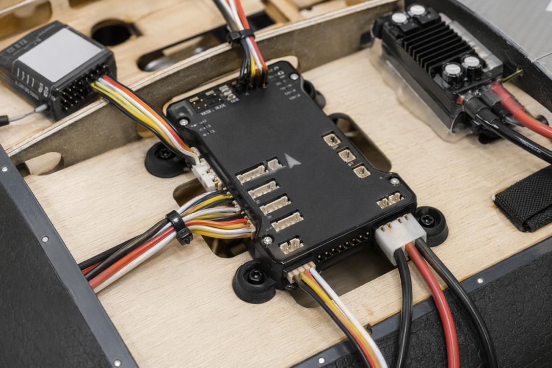
ESC power wiring:
- Solder XT60 connector to ESC power wires (thick red + black): red → XT60 positive (raised terminal), black → negative (flat terminal)
- Do not cut the BEC output wire — this provides 5V power to servos and flight controller
Multimeter mandatory checks (3 items):
- Battery connected: measure ESC input voltage → 3S full charge ≈ 12.6V, 4S full charge ≈ 16.8V
- Measure BEC output (red to black) → 5.0V ± 0.2V
- Power disconnected: measure ESC input positive to negative → no continuity. Buzzer indicates short circuit — do NOT power on.
Hard lesson: A reversed XT60 solder joint caused the ESC to smoke on first power-up. Photograph every joint and double-check red→positive, black→negative. This five-minute check saves a full electronics set.
Flight controller wiring — what plugs where:
Using Pixhawk 2.4.8 and Matek F405-WING as the two most common flight controllers.
Flight controller power:
Pixhawk 2.4.8 POWER port (6-pin white connector, left side of FC) to power module:
| Pin | Signal | Color |
|---|---|---|
| Pin 1-2 | VCC 5V output | Red |
| Pin 3-4 | Current sense positive/negative | Yellow/White |
| Pin 5-6 | GND | Black |
Matek F405-WING has onboard 5V/2A BEC output via board pads — direct power to the flight controller.
Multimeter check: Battery connected, measure FC power input → 4.8-5.2V
Servo signal wiring — fixed-wing unique complexity:
Multirotors plug four motors into MAIN OUT and are done. Fixed-wings must connect four servos to specific channels, with the motor ESCs on the throttle channel.
Standard fixed-wing channel mapping (ArduPlane firmware):
| Port | Channel | Controls | Connect |
|---|---|---|---|
| MAIN OUT 1 | CH1 | Ailerons | Left/right aileron servos (Y-cable if separate) |
| MAIN OUT 2 | CH2 | Elevator | Elevator servo |
| MAIN OUT 3 | CH3 | Throttle | ESC signal wire |
| MAIN OUT 4 | CH4 | Rudder | Rudder servo |
Twin-motor: second ESC signal wire to MAIN OUT 5. ArduPlane: SERVO5_FUNCTION=73 (right throttle).
3-pin orientation: Signal (white/yellow) toward the inner pin row, ground (black/brown) toward the outer edge. Reversing the connector won’t damage hardware but the signal won’t reach the FC.
Top 2 fatal wiring errors:
Error 1: Ailerons wired in same direction. Both ailerons deflect the same way — the aircraft spins on its roll axis. Crash within 2 seconds. Emergency fix: In Mission Planner, move the aileron stick and verify the two ailerons deflect in opposite directions.
Error 2: Elevator and rudder swapped. Pulling the elevator stick makes the aircraft yaw; pushing the rudder stick makes it pitch. Complete loss of control. Emergency fix: In Mission Planner, test every channel individually and confirm each stick corresponds to the correct surface.
GPS module:
- Mount GPS on a plastic mast with hot glue at the nose position
- GPS antenna faces skyward, minimum 5cm above the fuselage surface
- GPS cable plugs into the FC GPS/I2C port
Fixed-wing specific note: During flight, pitch angles reach ±30°. The GPS antenna must have completely clear sky view. Do not mount under the wing or in the fuselage shadow zone.
Airspeed sensor (fixed-wing exclusive):
Fixed-wings generate lift through forward speed. Insufficient speed → stall → nose-down descent → crash.
Selection: MS4525DO digital airspeed sensor (I2C) or MPXV7002DP differential pressure sensor with pitot tube.
Installation:
- Pitot tube (thin metal tube, front opening) mounts on the nose side, opening facing forward, extending 5cm+ ahead of the airframe
- Connect pitot tube to the airspeed module via silicone tubing
- Airspeed module plugs into the FC I2C port
Fatal error: Pitot tube opening facing backward or downward — the FC reads zero airspeed, thinks the aircraft has no speed, and continuously increases throttle. The aircraft overspeeds and becomes uncontrollable.
Self-check: After installation, blow into the pitot tube opening. Mission Planner should show increasing airspeed.
Flight controller mounting position:
Critical: Do NOT mount the FC near the tail or motor! Motor vibration is most severe at the tail. The FC is extremely sensitive to vibration — a poorly mounted FC causes altitude wobble in altitude-hold mode, position drift in loiter mode, and noisy sensor data.
- Mount the FC forward in the fuselage (as close to CG as possible)
- Two layers of 3M EVA foam padding underneath (approximately 3mm total), secure with zip ties or Velcro
- EPP foam airframes: do not screw-mount the FC — it cracks. 3D-printed airframes: use vibration-dampening mounting screws
- FC arrow points toward the nose, deviation under 5°
Safety switch and buzzer:
| Peripheral | Port | Notes |
|---|---|---|
| Safety switch | SW1 (FC top) | 2-pin white, orientation arbitrary |
| Buzzer | BUZZER (FC top) | 2-pin white, orientation arbitrary |
Initial power-on check:
Connect battery, wait 10 seconds:
- FC LED alternating red/blue → normal startup
- GPS blue flashing → searching for satellites
- Safety switch red flashing → normal (press and hold 3 seconds to arm → steady on)
- Buzzer double short beep → initialization complete
- All servos auto-center — control surfaces return to neutral
Servos not centering or jittering → insufficient power or poor signal contact. Check BEC output for 5V and signal wire seating.
6. Transmitter Binding and Control Surface Verification
Receiver binding:
Methods vary by brand but the principle is universal: receiver enters bind mode → transmitter sends pairing signal → solid red LED indicates completion.
Common methods:
- Frsky XM+/R-XSR: Insert bind plug into B/VCC port, power on → red fast flash → transmitter bind mode → solid LED
- ELRS receivers: Enter bind mode automatically on first power-up (first 60 seconds) → transmitter sends binding packet → WiFi flashing indicates completion
Receiver signal wire → FC RC IN port. SBUS mode recommended (more reliable than PPM).
Transmitter configuration:
Critical: select “Fixed-Wing” model type. Do NOT select multirotor! Fixed-wing and multirotor have completely different channel mappings — selecting the wrong type reverses every control surface.
Fixed-wing Mode2 (left-hand throttle) channel mapping:
| Channel | Controls | Stick | Correct response on push |
|---|---|---|---|
| CH1 | Ailerons | Right stick horizontal | Push right → right aileron up, left aileron down |
| CH2 | Elevator | Right stick vertical | Pull down → elevator up (nose pitches down) |
| CH3 | Throttle | Left stick vertical | Push up → throttle increases |
| CH4 | Rudder | Left stick horizontal | Push right → rudder deflects right |
Mission Planner control surface verification (life-saving step!):
Connect FC to computer, open Mission Planner (select ArduPlane, not ArduCopter!)
Navigate to Initial Setup → Mandatory Hardware → Servo Output
Test each surface:
| Action | Observe | Correct behavior |
|---|---|---|
| Right stick left | Left/right ailerons | Left up, right down |
| Right stick right | Left/right ailerons | Right up, left down |
| Right stick down | Elevator | Elevator up (nose pitches down) |
| Right stick up | Elevator | Elevator down (nose pitches up) |
| Left stick left | Rudder | Rudder left (nose yaws left) |
| Left stick right | Rudder | Rudder right (nose yaws right) |
Surface direction reversed? In Mission Planner Servo Output page, check “Reversed” for the affected channel. Aomway wiring harnesses use color-coded servo leads to reduce connection errors during build. Do not reverse in the transmitter — transmitter reversal affects all models, not just this one.
Neutral position adjustment: Sticks centered but control surfaces are misaligned? Loosen the pushrod lock nut, rotate the pushrod to adjust length. Target: all control surfaces flush with wing/stabilizer at neutral stick.
7. Center of Gravity — The Soul of a Fixed-Wing
Approximately 50% of fixed-wing crashes originate from CG errors. This step invalidates everything before it if done wrong.
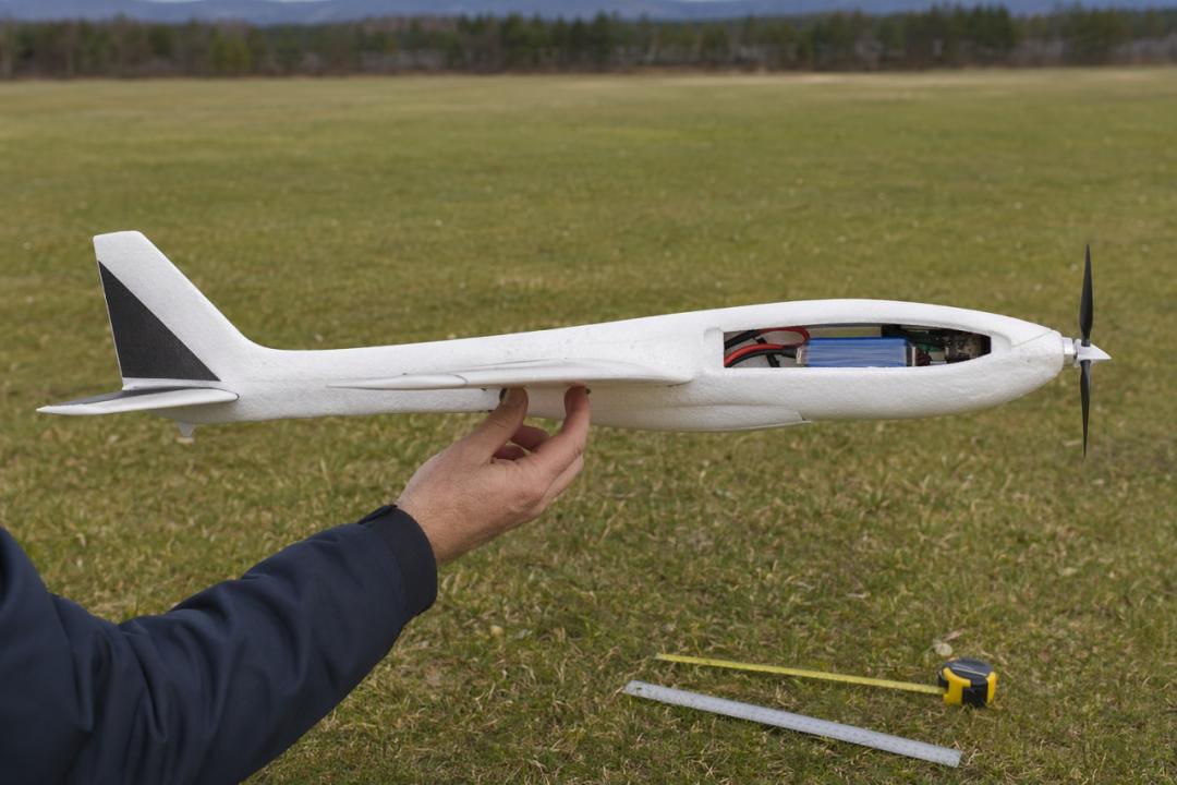
Why CG is critical:
- CG too far forward → aircraft constantly pitches down, elevator needs continuous up-trim, landing becomes nose-first
- CG too far aft → unstable, any disturbance triggers pitch oscillation or stall, especially dangerous for beginners
- Ideal CG → 25%-33% of wing chord from the leading edge at the widest point
CG reference by airframe type:
| Airframe | Wingspan | CG Reference | Tolerance |
|---|---|---|---|
| EPP foam trainer | 1.2-1.4m | ~40-60mm from LE at widest point | Generous (±10mm flyable) |
| 3D-printed long-range | 1.45m | ~50-65mm from LE at widest point | Tighter (±10mm needs attention) |
| 2m-class FPV platform | 2.0-2.2m | Per manufacturer drawing | Tight (±5mm) |
Finger CG check method (most practical):
Place your index finger under one wing at the widest point, ~25% chord from the leading edge. Support the fuselage bottom with your thumb. Slowly move your fingertip forward or backward until the aircraft balances level — neither nose-down nor tail-down. Mark this position — this is your CG.
CG adjustment:
| Condition | Fix |
|---|---|
| Nose heavy (CG forward) | Move battery backward |
| Tail heavy (CG aft) | Move battery forward |
| Moved battery fully but still off | Add nose weight (coins, lead weights with 3M tape) |
Golden rule: Check CG before every flight. If it is not checked, do not fly.
Motor test:
Mission Planner → Motor Test, click Test Motor — motor spins at low speed.
Single motor: Viewed from behind, the propeller must blow air backward. Air blowing forward means wrong rotation direction — power off, swap any two of the three motor phase wires.
Twin motors: Both motors must rotate in opposite directions. Same fix — swap phase wires on the motor with incorrect rotation.
Airspeed sensor calibration:
Mission Planner → Airspeed. With pitot tube unblocked and aircraft stationary, click Calibrate. Reading should be near 0 (±2 m/s). Readings above 5 m/s → pitot tube is blocked or installed backward.
Final pre-flight checklist (tick every item):
| Item | Standard | Method |
|---|---|---|
| All servos centered | Surfaces neutral | Visual |
| Aileron symmetry | Equal deflection angles | Protractor |
| Elevator neutral | Flush with horizontal stabilizer | Visual |
| Rudder neutral | Parallel to fuselage longitudinal axis | Visual |
| CG position | Per manufacturer spec | Finger CG method |
| Minimum throttle CH3≈1000 | ~1000 | Mission Planner |
| Maximum throttle CH3≈2000 | ~2000 | Mission Planner |
| Motor rotation direction | Per configuration requirement | Visual |
| Airspeed zeroed | 0±2 m/s | Mission Planner |
| FC LED solid green | Ready | Visual |
| GPS satellites >6 | Blue LED slows | Wait 2-3 minutes outdoors |
| Supply voltage | 4.8-5.2V (Aomway PDB tested) | Multimeter |
| Total weight | Within airframe specification | Digital scale |
All checked? Congratulations — the build is complete. Install the propeller!
8. First Flight Survival Guide
Fixed-wing test flights are fundamentally different from multirotor. Multirotors can hover if something goes wrong. Fixed-wings have no “pause button” once airborne.
Before takeoff (complete these on the ground, every item mandatory):
- Set flight mode to Manual or FBWA (stabilized assist). Do not attempt fully autonomous missions on the first flight
- Verify control surface response — every stick input must move the correct surface immediately, no delay
- Re-check CG — the battery may have shifted during handling
- Confirm airspeed zero reading
- GPS satellites >6 — fixed-wings are harder to recover than multirotors if lost
Hand launch (recommended for small fixed-wings):
Set throttle to approximately 70%. Launch horizontally forward (do not throw upward!). The aircraft should climb steadily.
- Nose drops immediately after launch → CG too far forward, move battery backward
- Nose rises then stalls → CG too far aft, move battery forward
Wheeled takeoff (airframes with landing gear or larger models):
Set throttle to approximately 80%. Wait for airspeed to reach 10-15 m/s before gently pulling back. Do not pull early! Insufficient speed + back elevator = stall and nose-dive.
Landing:
Aim for a clear open area. Reduce throttle to idle, maintain a straight approach, control descent rate with elevator. Gently pull back just before touchdown to slightly raise the nose. Maintain direction after touchdown, use rudder to correct roll-out. Twin-motor: reduce throttle on both sides simultaneously to prevent differential thrust from causing yaw.
Post-first-flight adjustments:
- Aircraft consistently banks to one side → check thrust line alignment — Aomway carbon motor mounts come pre-aligned to minimize this issue or control surface neutral position
- Needs back stick for level flight → CG forward, move battery backward
- Needs forward stick for level flight → CG aft, move battery forward
- Uneven aileron sensitivity between left and right → adjust MIN/MAX symmetry in Mission Planner
Crash Cause Ranking
| Rank | Cause | Percentage | Prevention |
|---|---|---|---|
| 1 | CG error | ~50% | Finger CG check every time |
| 2 | Reversed control surfaces | 20% | Mission Planner individual channel verification — Aomway servo extension sets include labeled connectors for easy channel identification |
| 3 | Pulling elevator before sufficient airspeed | 10% | Wait for airspeed to build before pitching up |
| 4 | Wrong motor direction / twin motors same direction | 5% | Motor Test confirmation |
| 5 | Airspeed sensor failure or reverse installation | 5% | Blow test + calibration |
| 6 | 3D-printed carbon rod not fully inserted | 3% | Pull outward after insertion to confirm |
| 7 | FC vibration-induced instability — use Aomway vibration-dampening FC mounts for critical builds | 2% | Mount away from motor, foam pad dampening |

Memory aid (bookmark this):
“CG, Surfaces, Airspeed, Rotation, Voltage, Center”
CG = center of gravity check, Surfaces = control surface direction verification, Airspeed = pitot calibration,
Rotation = motor direction confirmation, Voltage = multimeter voltage check, Center = servo neutral position
Survival rule:
“A multirotor assembled incorrectly can be repaired. A fixed-wing assembled incorrectly can only be buried.”
Spending five extra minutes on each check saves ten times that in rework and hundreds of dollars in crash damage.



Skill Progression Path
| Stage | What to Learn | Recommended Platform |
|---|---|---|
| Beginner | Assembly, CG balancing, hand-launch technique | EPP foam trainer 1.2-1.4m wing |
| Intermediate | FBWA stabilized flight, auto-tune, mission planning | Same trainer + airspeed sensor + telemetry |
| Advanced | 3D-printed long-range builds, FPV flight, survey/payload | Titan Comet class 1.4-2m |
Frequently Asked Questions
Q: Can I use a multirotor flight controller for fixed-wing?
A: Yes — controllers like Pixhawk and Matek F405-WING support both ArduCopter and ArduPlane firmware. However, a fixed-wing build requires an airspeed sensor, different servo channel mapping, and CG-based trimming that multirotors do not need.
Q: What is the biggest mistake beginners make on their first fixed-wing build?
A: CG error causes about 50% of first-flight crashes, followed by reversed control surfaces at 20%. Both are completely preventable with pre-flight checks. The Aomway field test protocol requires a full control surface sweep and CG confirmation before every flight.
Q: Is EPP foam durable enough for long-term use?
A: Yes. EPP (expanded polypropylene) foam is impact-resistant and does not shatter like EPS or Depron. Repairs are straightforward with foam-safe CA glue or hot glue. Many pilots fly EPP trainers for years before upgrading.
Q: How long does it take to build a fixed-wing from scratch?
A: EPP foam trainer with pre-cut slots: approximately 4 hours including wiring and testing. 3D-printed build: 8-12 hours of assembly (excluding 24-48 hours of printing time per part).
Q: Do I need an airspeed sensor for my first fixed-wing?
A: Strongly recommended. Without airspeed data, the flight controller cannot detect an impending stall. In manual mode, the pilot must judge speed by sight and sound — a skill that takes time to develop. A $15 airspeed sensor provides a critical safety margin that is well worth the investment. Aomway carries compatible airspeed sensor kits for standard Pixhawk and Matek flight controllers.

This place has quickly become my favorite spot for weekend entertainment. The loyalty program rewards me regularly and I never have to wait long for my winnings. Everything runs smoothly whether I am on my laptop or phone. Give it a try and you will not be disappointed. mm88chip