

Embedded Vision Engineering Notes · Technical Deep Dive · Control + Vision + Embedded Systems
Introduction
In many projects, YOLO detection runs fine and STM32 control runs fine — but the moment you integrate them, problems appear: the target bounding box jumps while the motor vibrates; model inference works but control lags noticeably; serial communication works but frame errors accumulate over continuous operation.
These issues are usually not caused by a single faulty module. They are symptoms of a system architecture that was not designed properly for control, vision, and embedded integration.
Abstract
Control, vision, and embedded systems often coexist in engineering projects such as robots, gimbal tracking, target recognition, edge AI detection, industrial sorting, and intelligent actuation systems. Each module works in isolation, but integrating them into a complete system exposes problems with latency, communication, synchronization, data formats, control cycles, task scheduling, and system stability. This article presents a complete fusion architecture — from visual perception, edge inference, target information extraction, embedded communication, control decisions, actuator output, to state feedback — from an engineering architecture perspective.
At Aomway, we face exactly these challenges when building FPV gimbals and video transmission systems: vision tracks the target, control keeps it stable, and the embedded layer makes it reliable in the field.
01 Why Is Fusion Harder?
Core conclusion: the difficulty of a fusion system is not whether one module is strong enough, but whether multiple modules can cooperate stably.
Working on vision alone, you focus on detection accuracy, inference speed, false positives and misses, model size, and deployment framework. Working on control alone, you focus on PID parameters, control cycles, feedback signals, actuator capability, steady-state error, and overshoot. Working on embedded alone, you focus on UART, interrupts, timers, DMA, PWM, ADC, and system stability.
But when you put them into one system, the problems take on a different shape.
Vision latency affects control stability. Bounding box jitter causes actuator jitter. Unreliable communication causes lost control commands. Control cycles and vision frame rates do not match. Edge devices and MCUs run at different task rhythms. One module stalling drags down the entire pipeline.
This is why many projects look fine in the demo phase but start showing random problems during integration, continuous operation, and real-world load.
Tech-media observation: a fusion system is not “connect YOLO, STM32, and PID together” — you must manage the data flow, control flow, and safety flow simultaneously.
02 How Should a System Be Decomposed?
Core conclusion: layer first, optimize second. If the layers are unclear, tuning will be painful later.
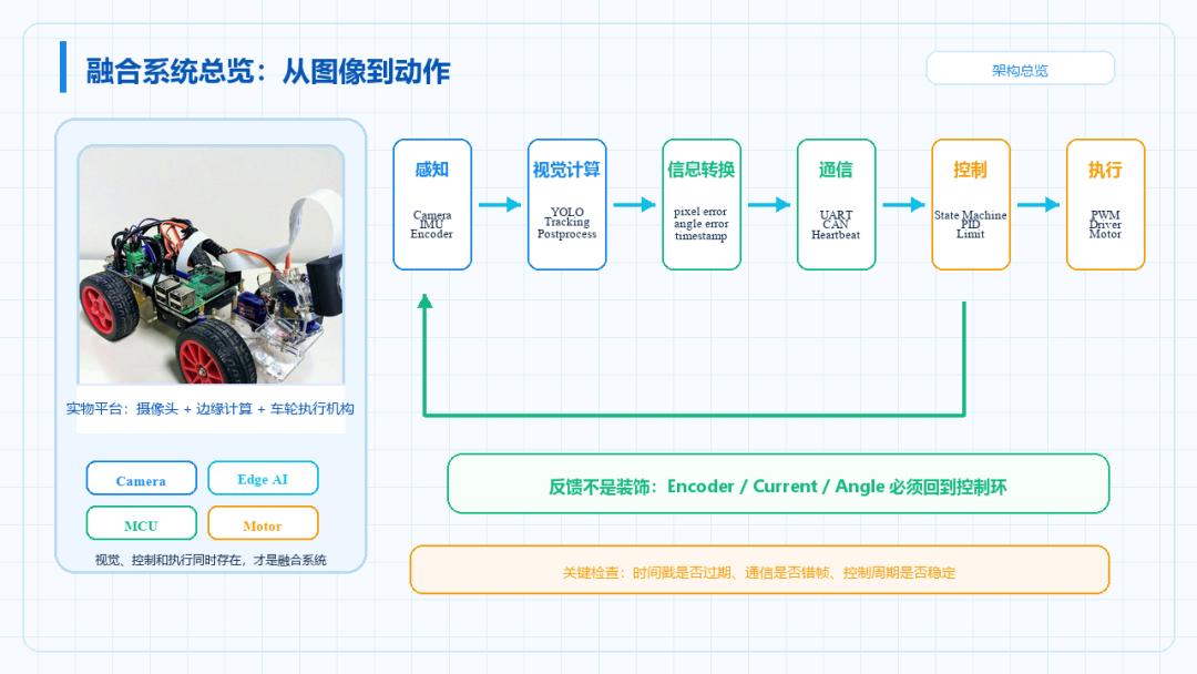
A control, vision, and embedded fusion system can be split into at least six layers.
Layer 1 — Perception. Collects external information: cameras, IMU, encoders, Hall sensors, LiDAR, ultrasonic, current, voltage, and temperature sensors.
Layer 2 — Vision Computing. Handles image capture, preprocessing, model inference, post-processing, target position extraction, and confidence filtering.
Layer 3 — Information Conversion. Converts vision results into quantities the control system understands: bounding box center, target deviation, angle error, distance estimate, target velocity, target-lost status, and control error.
Layer 4 — Embedded Communication. Links edge computing devices and MCUs via UART, CAN, RS485, Ethernet, SPI, USB, or ROS topics.
Layer 5 — Control Decision. Computes control output from target and feedback information: PID, state machines, filtering, saturation, dead-zone compensation, safety protection, and higher-level strategy when needed.
Layer 6 — Actuation Output. Drives real hardware: PWM, DAC, motor drivers, servos, gimbals, relays, solenoid valves, and mechanical actuators.
03 Vision Output Is Not a Control Quantity
Core conclusion: vision results must go through engineering conversion before entering the control loop.
Many people misunderstand: YOLO detects a target, so we can directly drive the motor.
That is not how it works.
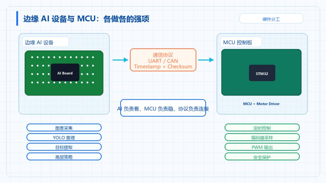
Model outputs are typically bbox, class, confidence, mask, keypoints, or tracking ID. These are not control quantities. What the control system actually needs is the target’s deviation from image center, angle error, distance error, velocity error, whether the target is inside the control region, whether output is permitted, and whether the target is lost.
Take gimbal target tracking as an example. The image center is:
(cx_img, cy_img)The target bounding box center is:
(cx_obj, cy_obj)The control error can be defined as:
ex = cx_obj - cx_img
ey = cy_obj - cy_img
This step looks simple, but it determines control direction, coordinate definition, sign conventions, and subsequent stability. If the x-direction sign is flipped, the system will diverge further and further. If image coordinates and mechanical coordinates are not unified, no amount of PID tuning will fix it.
04 Vision Latency Enters the Control Loop
Core conclusion: in vision-based closed-loop control, latency is not a minor issue — it is central to stability.
Vision systems are usually not real-time continuous signals. They are low-frequency, delayed measurement results.
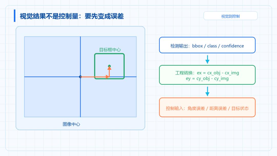
For example: camera at 30 FPS, model inference at 20 FPS, control loop at 100 Hz, motor feedback at 1 kHz, serial communication at 50 Hz. This means every vision result the controller uses may already be the target position from tens of milliseconds ago.
Latency sources are many: exposure, image capture, buffering, preprocessing, inference, post-processing, communication, control computation, and actuator response.
Typical problems: the target has moved but the controller is still chasing the old position; gimbal tracking oscillates back and forth; robot obstacle avoidance reacts slowly; vision-based closed loop oscillates more easily than standalone PID; error grows when the target moves fast.
In engineering, you should not just ask “what is the model FPS?” — you must also ask how long it takes from light entering the camera to the controller actually outputting an action.
05 Bounding Box Jitter Becomes Actuator Jitter
Core conclusion: vision detection results cannot be fed directly into the controller — they must first be stabilized.
Bounding boxes are not perfectly stable.
Even with a stationary target, the box may show center jitter, size variation, confidence fluctuation, occasional class changes, target ID jumps, and short detection drops.
If these results go straight into the controller, the control output will jitter too. Symptoms: the motor vibrates slightly near the target, the gimbal constantly micro-adjusts, actuators reverse frequently, control output is not smooth, and the system looks “neurotic”.
Solutions include target center filtering, dead zones, confidence thresholds, target-hold logic, lost-target state machines, tracking algorithms to smooth target position, and output rate limiting and saturation.
Note the trade-off: filtering reduces jitter but adds latency. In vision control systems, jitter and latency must be considered together.
06 Vision Is Low-Frequency, Control Is High-Frequency
Core conclusion: the vision thread and the control thread must not be merged into one loop.
A common mistake: every time vision detects a frame, control updates once.
That works in simple demos but is rarely stable in production systems.
A better design: the vision thread runs at camera/model speed; the control thread runs at a fixed period; the control thread uses the latest valid vision result; if the vision result times out, the system enters hold, degrade, or safe state.
For example: vision updates at 20 Hz, control updates at 100 Hz. The control thread executes every 10 ms, but vision results may only refresh every 50 ms. You must record the timestamp of the latest vision result, judge whether it is stale, and decide whether to keep using the old value, predict the target position, or stop output.
07 How Should Edge Devices and MCUs Divide Work?
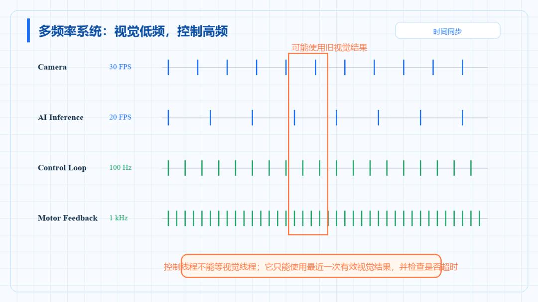
Core conclusion: edge devices are suited for perception and high-level decisions; MCUs are suited for real-time control and low-level actuation.
Fusion systems typically have two core compute units.
Edge AI devices may be Jetson, RK3588, industrial PCs, Raspberry Pi, or x86 mini-PCs. They are better at camera capture, image preprocessing, model inference, target detection, target information extraction, and high-level strategy.
MCUs may be STM32, ESP32, GD32, NXP, or TI C2000. They are better at timed control, PWM output, encoder capture, motor driving, safety protection, real-time closed loops, and low-level actuation.
We do not recommend having the Jetson handle high-frequency motor closed loops directly, nor having the STM32 run complex vision models. A more sensible architecture: the edge device handles “seeing” and “understanding”, the MCU handles “stability” and “execution”.
The communication protocol between them must be reliable. It must carry not only target deviation, but also target validity, confidence, timestamps, control mode, heartbeat packets, and checksums.
08 The Communication Protocol Connects Two Worlds
Core conclusion: the worst failure mode in a fusion system is “communication looks normal, but the data is already misaligned or stale”.
What the edge device sends to the MCU may include: target deviation, target angle, target distance, control mode, target-found flag, target confidence, tracking ID, and timestamp.
What the MCU sends to the edge device may include: current angle, current speed, motor state, voltage and current, fault codes, control mode, and heartbeat packets.
The protocol should include a frame header, length, command word, data area, timestamp, checksum, timeout detection, and error counters.
Once you enter closed-loop control, you cannot rely on “the serial port receives data” to judge that communication is healthy. What matters more: is the data complete, is it stale, does it come from the same coordinate definition, and does it match the current control state?
09 Safety Must Not Depend on Vision
Core conclusion: vision can participate in control, but it cannot be the only safety basis.
Vision systems can fail. Targets are lost, models misdetect, cameras disconnect, lighting changes, confidence drops, communication breaks, and edge devices can hang.
If the control system depends entirely on vision results, it becomes dangerous.
You must design independent safety mechanisms: stop control when vision results time out; enter search or hold mode when the target is lost; do not update control when confidence is low; MCU auto-stops when communication drops; actuator output is saturated; emergency stop has the highest priority; a watchdog monitors communication heartbeat; state machines manage control modes.
A truly mature system is not one where vision is always correct — it is one that stays safe when vision is unreliable.
10 Recommended Debugging Sequence
Core conclusion: fusion system debugging must be done in stages. Do not mix all problems together.
Stage 1 — Vision pipeline. Check camera stability, bounding box correctness, target center jitter, inference frame rate stability, and acceptable vision latency.
Stage 2 — Information conversion. Check pixel error calculation, coordinate direction consistency, angle conversion correctness, and target-lost handling.
Stage 3 — Communication link. Check UART/CAN stability, protocol checksums, data misalignment, timeouts, and whether the MCU receives the same data as the AI side.
Stage 4 — Control loop. Check fixed control period, stable PID input, output saturation, correct actuator direction, and trustworthy sensor feedback.
Stage 5 — System integration. Check whether vision latency affects control, whether output jitters, whether target loss is safe, and whether long-duration operation is stable.
11 Common Misconceptions
Misconception 1: detecting the target means you can directly drive the motor.
No. The bounding box is only a vision result — it must still be converted into error, state, and control input.
Misconception 2: higher vision frame rate means more stable control.
Not necessarily. What matters more is latency, jitter, timestamps, and control-cycle matching.
Misconception 3: the Jetson is powerful enough to replace the MCU for all control.
Not recommended. High-frequency real-time control belongs on the MCU.
Misconception 4: if the serial port receives data, communication is fine.
Not enough. You must also check checksums, timeouts, misalignment, timestamps, and target state.
Misconception 5: a good model means the system will be stable.
Not necessarily. Fusion systems must also handle task scheduling, control cycles, safety states, and long-term operation.
Summary
A control, vision, and embedded fusion system is not simply connecting a camera, a model, an STM32, and a motor.
What actually needs to be designed: how vision results become control error, how low-frequency vision integrates with high-frequency control, how edge devices and MCUs divide work, how the communication protocol guarantees reliability, how the control system handles latency and jitter, how the system enters a safe state when the target is lost, and how the whole system is debugged in stages and operated long-term.
In one sentence: vision is responsible for seeing the target, control is responsible for stable execution, and the embedded layer is responsible for running the system reliably.
In the next article, we will discuss how the control system should handle filtering, dead zones, and target hold when the vision bounding box jitters.
If you have any questions about this topic, feel free to contact us at [email protected]
