
Key Takeaways
- Two nonlinear MPC guidance laws, CR-MPC and MPCC, flew a small fixed-wing UAS along four tight 3D Lissajous paths.
- Both cut mean path error well below a lookahead baseline: on path 2, 6.372 m and 6.984 m versus 13.245 m.
- CR-MPC used a fixed 25 m/s reference progression rate; MPCC optimised the rate online and reached higher ground speeds.
- Guidance ran at 10 Hz on a Jetson Xavier NX, with every solve finishing inside the 100 ms control period.
- Neither controller has a terminal cost or constraint, so stability and recursive feasibility are observed experimentally, not proven.
Fixed-wing path following asks a deceptively simple question: given a smooth three-dimensional curve, how close can a small fixed-wing UAV fly to it while still moving fast along it? This 2026 paper answers it with two nonlinear model predictive control guidance algorithms — CR-MPC (Constant Rate MPC) and MPCC (Model Predictive Contouring Control) — validated in real flight against a lookahead guidance baseline.
Reference: C. Alexander Hirst, Chris Reale and Eric Frew, 3D Path-Following Guidance via Nonlinear Model Predictive Control for FW-sUAS, arXiv:2512.24326v1, 30 December 2025.

Why Tight 3D Paths Are Hard for a Fixed Wing
The paper groups the difficulties into three areas.
- Vehicle dynamics: nonlinear, high inertia, low thrust-to-weight ratio.
- Real flight and onboard conditions: limited sensor and actuator accuracy, wind disturbance, constrained onboard compute.
- Existing guidance methods: typically designed for simple path classes and therefore conservative, with the airspeed setpoint fixed in advance by the operator, which caps how fast the aircraft can progress along the path.
Modern planners can already generate the complex 3D paths a mission needs; executing them is where guidance falls short.
Path following differs from position tracking in one important way: it does not require the aircraft to reach a specific point on the path at a specific time. But for a general curve, the nearest point on the path is itself a non-convex optimisation problem, which makes it expensive to re-solve efficiently inside every step of the prediction horizon.
Direct-actuator MPC has been demonstrated, but it demands detailed aerodynamic modelling, and the roughly 100 Hz actuator update rate is a real burden for embedded computing. Some earlier 3D MPC work was never flight-tested under realistic disturbance, compute limits, sensor noise and model mismatch; the one prior study that did fly relied on a lookahead algorithm to generate references, was restricted in the paths it could handle, and flew at a fixed reference airspeed.
A Control-Augmented Model Instead of Direct Actuator Control
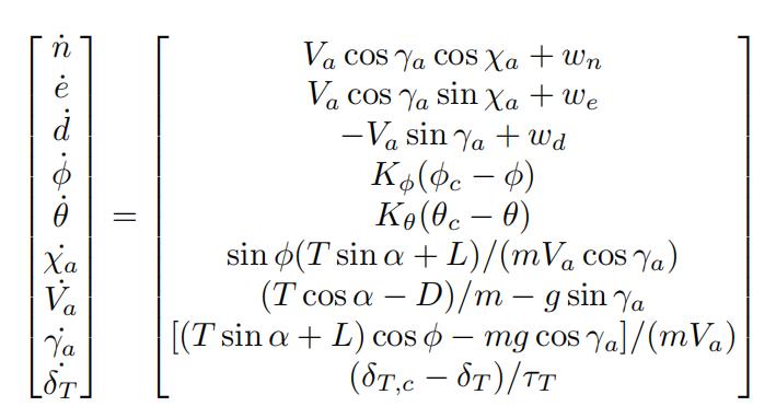
The paper uses a control-augmented dynamics model that wraps the low-level attitude stabiliser. Compared with commanding actuators directly, this guidance-level model tolerates a lower command update rate and is easier to identify from a modest amount of flight data.
PX4’s native guidance treats lateral control separately from altitude and airspeed. The MPC guidance controller here combines the aircraft’s attitude-controlled dynamics, longitudinal dynamics and the coupled lateral-longitudinal kinematics, sending roll, pitch and throttle setpoints to the underlying autopilot.
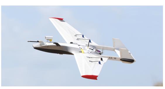
The test aircraft is a RAAVEN carrying a suite of atmospheric sensors, seen here flying a low pass during a scientific field campaign.
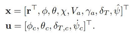
It uses a Cube Orange flight controller running PX4 v1.13.1. The model state covers three-dimensional position, roll, pitch, air-relative heading, true airspeed, air-relative flight path angle and a virtual throttle. The inputs are roll, pitch and throttle commands. The model assumes the low-level autopilot keeps sideslip near zero, and the closed-loop attitude response plus the lift, drag and thrust parameters are fitted from flight data.
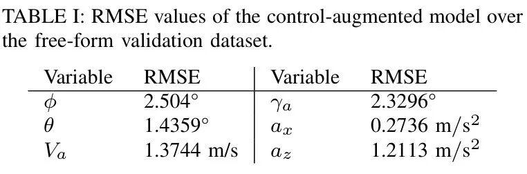
Thirty-eight minutes of flight data were logged at 40 Hz, split 80/20 into training and test sets. Open-loop aerodynamic and power parameters and closed-loop attitude parameters were fitted separately in a grey-box approach, then the complete model was validated on free-form flight data. The validation RMSE is shown below; the authors caution that grey-box aerodynamic parameters fitted to output error do not necessarily correspond to real physical quantities.

| Variable | RMSE | Variable | RMSE |
|---|---|---|---|
| φ (roll) | 2.504° | γa (flight path angle) | 2.3296° |
| θ (pitch) | 1.4359° | ax | 0.2736 m/s² |
| Va (airspeed) | 1.3744 m/s | az | 1.2113 m/s² |
Two Ways to Define the Reference Path
The reference path is preprocessed into an arc-length-parameterised B-spline with C² continuity.
CR-MPC: a constant progression rate
CR-MPC first computes the nearest path parameter to the aircraft’s current position, then advances at a preset constant reference path parameter rate across the prediction horizon. The next call re-establishes the initial reference point, so even if the scheduled progression speed is unachievable, the controller still adapts to the actual flight state.
MPCC: optimise the progression rate
MPCC borrows from model predictive contouring control and makes the path parameter and its rate part of the decision variables. It optimises the reference progression rate online, which lets a weight trade path error against higher airspeed, at the cost of more computation. The airspeed error term encourages higher airspeed, and the larger the weight μ, the more it favours speed; the final prediction stage sets μ to zero to strengthen the path error term at the end. MPCC also hard-constrains the path parameter rate to encourage progress at least at some minimum rate.

Cost Function, Flight Constraints and Online Solution
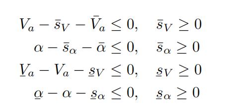
CR-MPC’s error terms cover three-dimensional position error, horizontal track angle error and flight path angle error. The objective also penalises attitude and throttle rates, successive control command changes and soft-constraint slack. Airspeed and angle of attack are soft-constrained, so the controller strongly prefers to stay inside the acceptable flight envelope while tolerating brief excursions caused by model mismatch, measurement noise or changing wind. Roll, pitch and throttle commands are hard-constrained. MPCC uses a similar formulation with the path progression and airspeed objectives added.
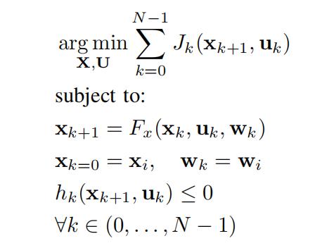
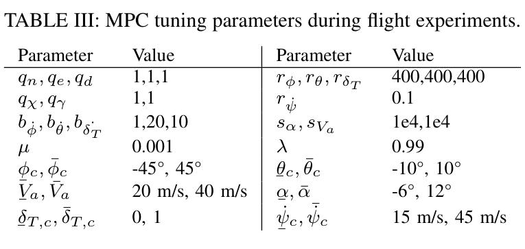
Both controllers are implemented with acados and CasADi using sequential quadratic programming with a real-time iteration scheme: only one SQP iteration is executed before returning a control signal, trading solution accuracy for feedback rate. The nearest path point is found by a K-D tree query at initialisation and by a local search around the previous nearest point thereafter. The prediction horizon is 5 seconds at 0.1 second steps — 50 stages — and guidance updates at 10 Hz.
The paper states plainly that this truncated MPC has no terminal cost or terminal constraint, and therefore no provable stability or recursive feasibility. The stable behaviour of both controllers over longer horizons is an experimental observation. The vehicle model also depends on airspeed remaining positive and on the flight path angle staying in the range where the dynamics are defined.
Flight Test Setup
Model identification and guidance comparison were two separate test campaigns. The first used free-form manoeuvres to check the control-augmented model’s predictive capability. The second took place in Arvada, Colorado, with a light south-easterly wind varying between 2 and 5 m/s.
The baseline was a lookahead guidance controller previously tuned in flight, with a 4 second lookahead time and airspeed held at 21 m/s by a PID loop. All three algorithms ran on a Jetson Xavier NX companion computer connected to the Cube Orange over a wired serial link.
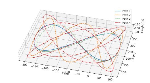
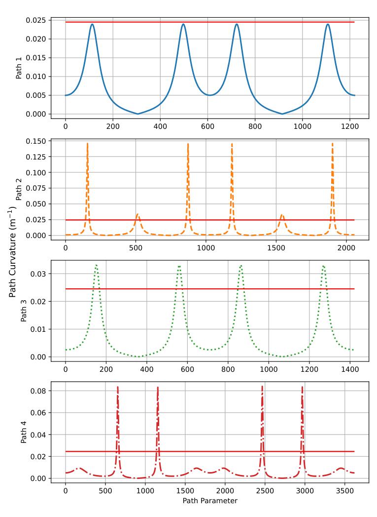
Four Lissajous curves were selected: paths 1 and 2 at 100 m altitude, paths 3 and 4 varying between 80 and 120 m each lap. RAAVEN’s coordinated turn radius is 40.8 m at 20 m/s airspeed and 45° maximum bank. Path 1 has a minimum curvature radius of 41.7 m; paths 2, 3 and 4 have 6.9, 30.2 and 11.9 m respectively. Path 3 also demands a maximum flight path angle of 8.4°. Each controller flew two consecutive laps of each path to reduce the influence of changing wind, and CR-MPC’s reference progression rate was fixed at 25 m/s with all other MPC parameters held constant across paths.
Path Error and the Turn Manoeuvre
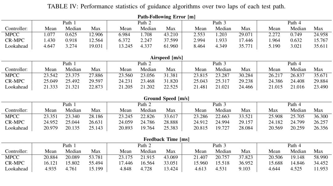
Across all four paths, both MPC controllers achieved lower mean path error than lookahead guidance. On path 2 the mean errors were 6.984 m for MPCC, 6.372 m for CR-MPC and 13.245 m for lookahead. On path 3 they were 2.553 m, 2.994 m and 8.464 m.
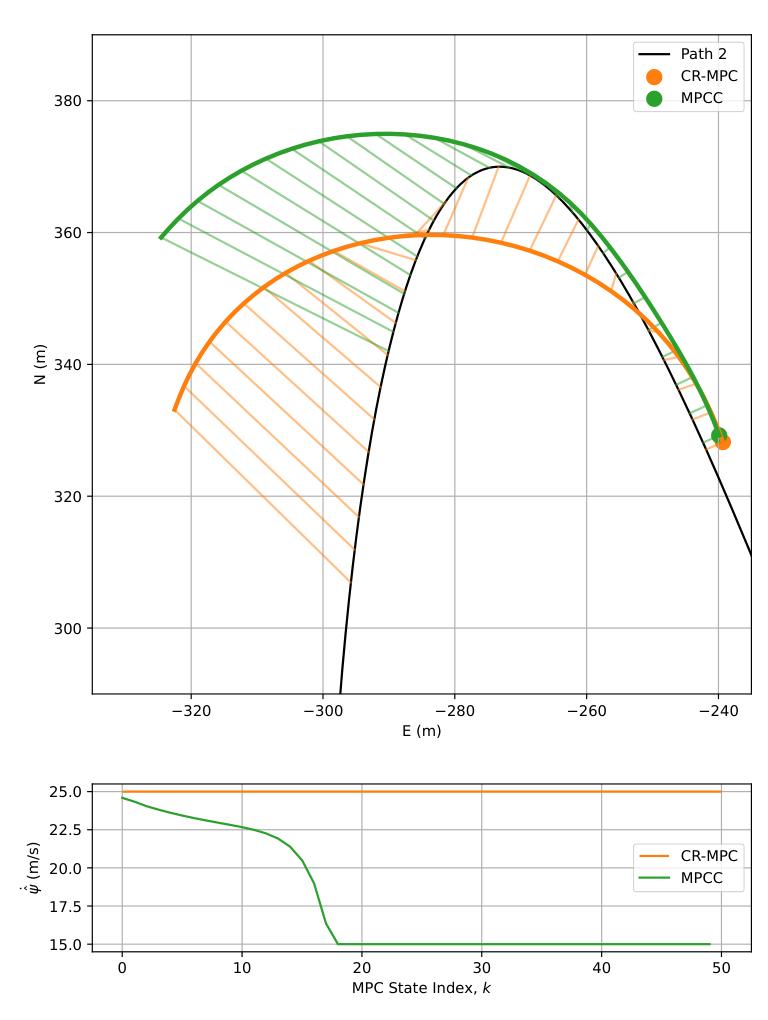
The paper attributes the difference to MPC controlling pitch and throttle together, actively modulating airspeed, and using the longer horizon to slow down before a tight turn so the turn radius shrinks.
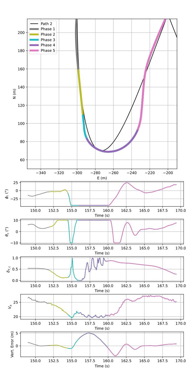
In the tight turn on path 2, both controllers produced a sequence of roll, pitch and throttle actions. Five phases appear in the flight data: approaching the turn at high airspeed; throttling back and pitching up to decelerate; entering the turn with a steep bank and a brief nose-down to hold airspeed while losing altitude; pitching up at maximum bank to minimise turn radius; then re-establishing attitude back onto the path. None of these actions is explicitly programmed into the control law — they fall out of solving the optimal control problem online.
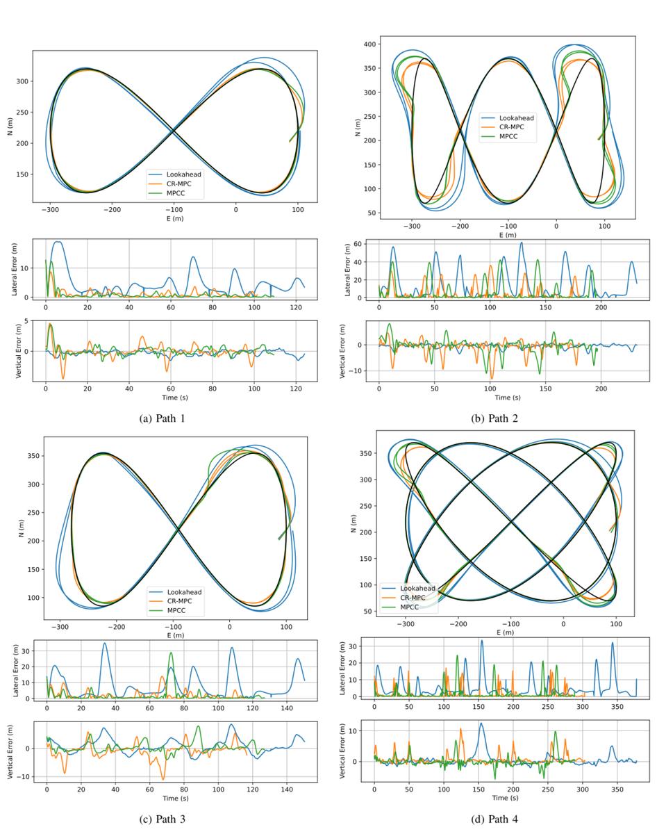
The trajectory comparison also exposes a trade-off. On paths 1, 2 and 4 the MPC controllers had smaller lateral path error but larger vertical path error than lookahead guidance. The authors attribute this to the objective weighting lateral and vertical error equally; path 3, which demands more aggressive longitudinal manoeuvring, is where MPC’s active pitch and throttle modulation tracked the vertical reference better.
CR-MPC vs MPCC
The two controllers produced very close mean and median path error, ground speed and airspeed statistics. Wind variation and gusts make the small differences insufficient to declare an overall winner.
CR-MPC’s fixed reference progression rate encourages corner-cutting: on paths 1 and 3 that increases path error, while on the tight turns of paths 2 and 4 it helps. CR-MPC had the lower maximum path error on all four paths.
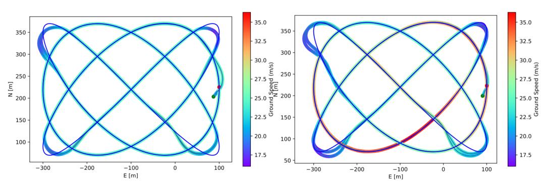
MPCC adjusted its reference progression rate on its own and showed a wider ground-speed range on path 4, where CR-MPC’s was narrower. MPCC reached a higher maximum ground speed on all four paths, with the highest ground speed in the whole campaign at 36.300 m/s. The authors cite large-area mapping and severe-storm research as two mission types that may need different controller characteristics — one wanting steady ground speed, the other wanting adaptation to changing wind.
Safety Envelope, Real-Time Behaviour and Limits of Validity
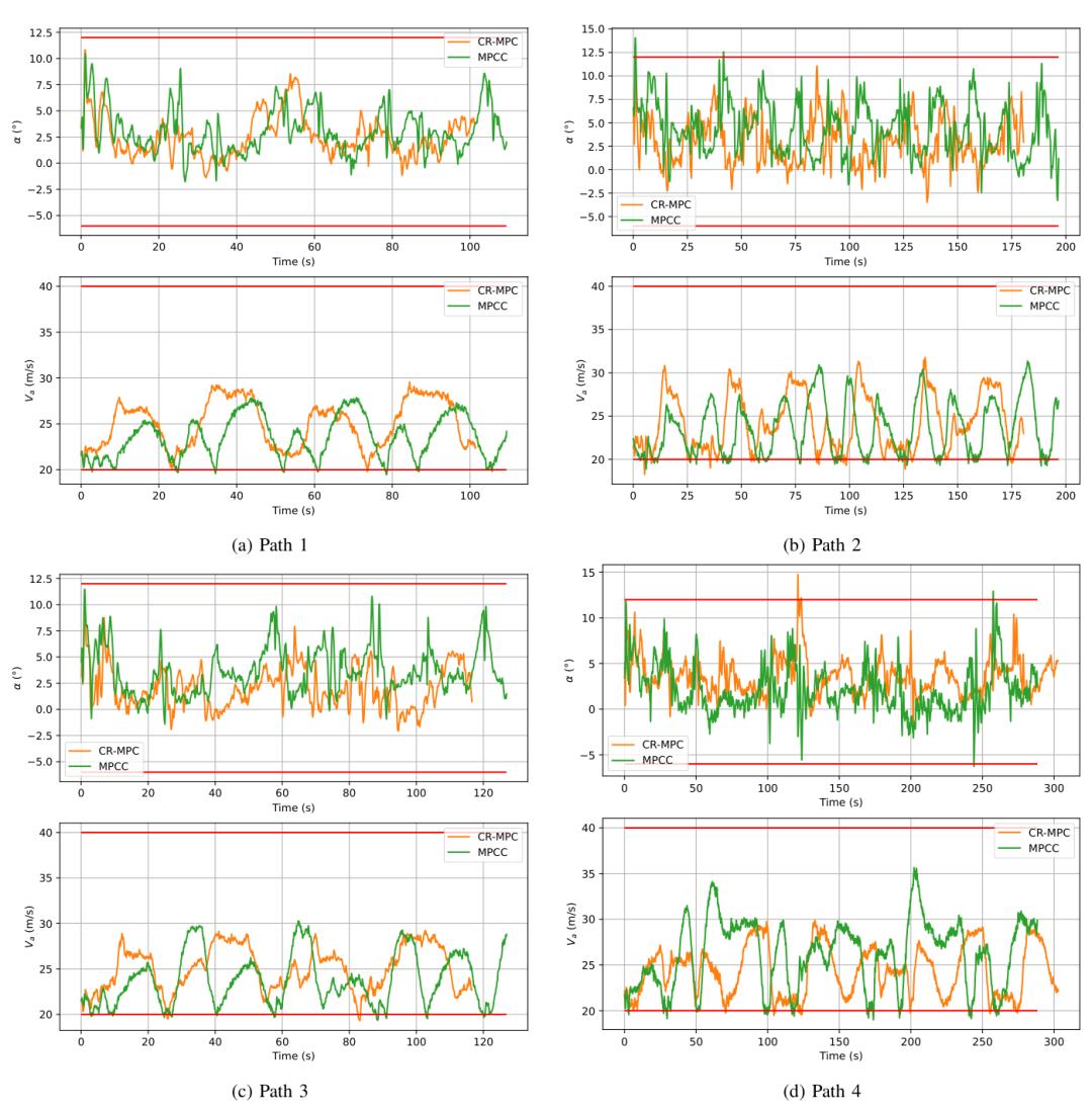
Despite sensor noise and model mismatch, both controllers kept airspeed and angle of attack broadly inside the preset safe envelope through the soft constraints; the tight turns on paths 2 and 4 came closest to the boundaries. The test lead’s qualitative assessment was that all algorithms behaved normally and safely on every path, with no manual takeover required.
CR-MPC’s mean feedback time was more than 20% lower than MPCC’s on every path. Even though MPCC has more optimisation variables, the longest feedback time for either controller stayed below the 100 ms that a 10 Hz control period allows, which is the paper’s evidence for onboard real-time feasibility.
These results apply to the RAAVEN platform, the four test paths and a 2–5 m/s wind. The authors use PX4’s horizontal wind estimate and assume the vertical wind component is zero when computing; applicability to more complex vertical wind fields needs further work, including three-dimensional wind measurement. The severe-storm study they cite is a potential application, not a strong-wind result validated in this campaign.
Conclusions
The paper develops and flight-tests two MPC guidance algorithms for high-performance path following along smooth 3D curves. The control-augmented model identified from RAAVEN flight data balances predictive capability against computational cost and suits MPC guidance. CR-MPC follows the path with a fixed progression speed; MPCC trades airspeed against path error. Both send roll, pitch and throttle setpoints to the underlying autopilot, guiding laterally and longitudinally at once, and both keep the aircraft in a safe flight state through soft constraints despite measurement noise and model mismatch.
The authors propose improving onboard sensing and modelling, and exploring a meta-level policy learned from data to reduce computational cost and improve closed-loop performance.
Have questions about this article? Feel free to contact us at [email protected] — we’re happy to help!
Frequently Asked Questions
What is the difference between path following and trajectory tracking?
Path following does not require reaching a specific point at a specific time — it only asks the aircraft to stay close to the curve while progressing along it. That extra freedom is what lets an MPC controller trade speed against path error.
How much better is NMPC than lookahead guidance?
Roughly two to three times lower mean path error on the paths tested: 6.372 m versus 13.245 m on path 2, and 2.553 m versus 8.464 m on path 3. The gain comes from controlling pitch and throttle together rather than flying a fixed airspeed.
Can this run on a companion computer in real time?
Yes, at 10 Hz. Both controllers ran on a Jetson Xavier NX with one SQP iteration per solve, and every solve finished inside the 100 ms control period, with CR-MPC more than 20% faster than MPCC.
Why does the controller slow down before a tight turn?
Because turn radius scales with airspeed. Using its 5-second horizon, the controller throttles back and pitches up before the turn, which shrinks the radius it needs and keeps path error down.
Is the controller proven stable?
No. The formulation has no terminal cost or terminal constraint, so neither stability nor recursive feasibility is guaranteed. Stable behaviour over the tested horizons is an experimental observation, and the authors say so explicitly.
About Aomway
Aomway has been developing and manufacturing video transmission and UAV radio hardware for over 15 years, producing equipment for any frequency band from 1 GHz to 9 GHz at power levels from 3W to 15W. We build high-power FPV video transmitters, directional and circularly polarised antennas, digital links, fiber-optic tether systems and detection hardware for pilots, integrators and commercial operators worldwide.