Building an Open Source Gimbal Controller: Why This Matters
After sharing the motor driver and IMU module schematics previously, today we complete the trilogy with the main control board design. This is the brain of any brushless gimbal system — responsible for sensor fusion, attitude estimation, and PID motor control. At Aomway, we appreciate clean, well-documented open hardware designs that bridge the gap between hobbyist experimentation and professional-grade FPV systems.
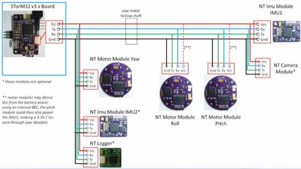
The board is designated as the NT Brushless Gimbal Controller (NT-BGC) — the core processing unit in the three-board gimbal architecture. Here are the key specifications:
| Parameter | Specification |
|---|---|
| MCU | STM32F103RC @ 72 MHz |
| Voltage Regulator | 5V / 0.6A low-noise switching regulator |
| Onboard IMU (SPI) | MPU9250 or MPU6500 |
| Communication | 2 × NT ports, 1 × NT-X port |
| Expansion | UART2, CAN bus (deprecated) |
| USB-to-Serial | Not included (removed from original) |
| RC Protocols | Futaba S-Bus, CRSF, Spektrum Satellite |
| PWM/PPM | Up to 4 PWM/Sum-PPM input/output channels |
| Joystick Interface | 2-axis joystick port |
| Auxiliary Ports | 2 × AUX ports, BUT port |
| Input Voltage | 6–27V (2–6S LiPo) |
| Motor Current | Depends on NT motor module used |
1. Microcontroller Design
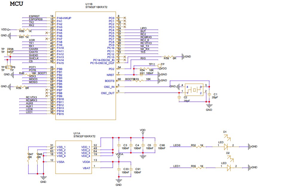
The heart of the board is the STM32F103RCT6 — an ARM Cortex-M3 core running at 72 MHz in an LQFP64-10×10 package. The circuit is essentially a minimal system with all peripheral interfaces broken out.
Key architectural notes:
- The IMU module handles raw sensor data acquisition only — no onboard computation. Pay attention to the raw data range and scaling factors.
- The BGC main controller receives motor encoder and IMU data, then performs attitude estimation and PID motor control — this is where the real-time control loop runs.
Current MCU upgrade path: STM32H7A3RG @ 280 MHz — offering significantly more headroom for advanced filtering algorithms and higher control loop rates that professional gimbal systems like Aomway’s require.
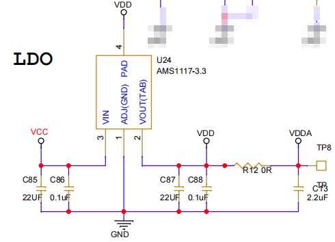
Power supply: Straightforward 5V-to-3.3V regulation via AMS1117-3.3 (fixed 3.3V output, 1A, SOT-89 package). A cautionary note: this regulator has inconsistent pinouts across manufacturers — particularly the fourth pin configuration. The design uses UMW’s AMS1117-3.3S variant. Always double-check the datasheet before substitution.
2. External Interfaces
Beyond sensor data processing, the controller needs robust external communication. The board provides:
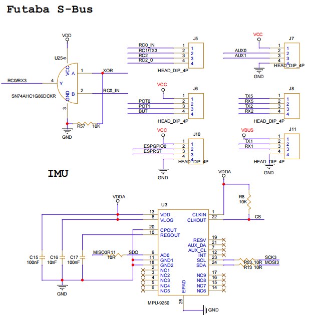
- Serial (UART): Connector J11 exposes TX1/RX1/VBUS for PC-based configuration tools. TX2/RX2 and RX5/TX5 provide additional UART channels for communication with external host processors, enabling remote parameter adjustment — a feature particularly useful for Aomway’s long-range gimbal setups.
- S-Bus: RC0_IN incorporates an inverter stage, enabling direct S-Bus protocol communication for industry-standard radio control systems.
Additional interfaces support external RC receiver connections for PWM-based per-axis gimbal control. Notably, TX2/RX2 and RX5/TX5 have been verified to function identically to TX1/RX1 for PC configuration — providing flexible routing options in tight builds.
3. Power Distribution
The VCC rail feeding the motor and IMU modules is generated on the main control board via a DC-DC converter. The original design used the MT2492 with a 4.5–16V input range and 2A maximum current capability. For builds requiring higher voltage tolerance, the JW5026 offers a pin-to-pin drop-in replacement supporting up to 40V input at 1A — a worthwhile upgrade for 6S LiPo systems.
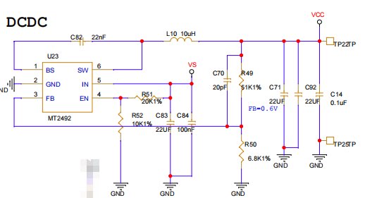
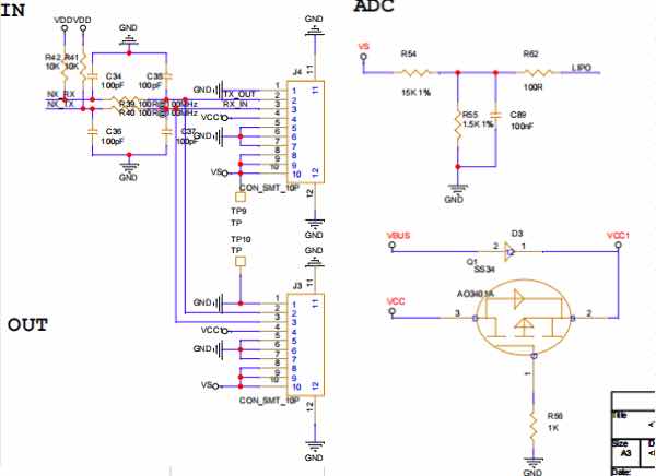
Additional power circuitry: The NT bus interface carries a 12V motor supply rail. Battery voltage sensing via a resistor divider enables low-voltage detection and safe shutdown. A diode-and-MOSFET power selector allows convenient Type-C powered debugging without disconnecting the main battery.
4. PCB Layout Tips
The board uses a simple two-layer design with components placed only on the top side — a deliberate choice that makes hand-soldering feasible for prototyping and small-batch production. This is a practical decision that we at Aomway respect: manufacturability matters as much as schematic elegance.
5. Open Source Repository
After organizing and verifying the design, the complete hardware package is now available on Gitea. The entire design is built upon the open-source Storm32 gimbal hardware platform, maintaining 100% firmware binary compatibility.
The system consists of three boards: Main × 1, Motor × 3, IMU × 1 — all verified on physical hardware and confirmed fully operational.
Repository: https://gitea.com/lhb/OpenStorm32-Gimbal.git
Development Roadmap
- Source and document a compatible motor on Taobao, then design the mechanical gimbal structure around it for a complete 3-axis assembly
- Develop custom IMU driver code based on the NT bus protocol understanding, enabling arbitrary IMU module swaps
- Replace the motor driver firmware while maintaining NT bus compatibility with the BGC controller
- Port the BGC main controller to a custom implementation — still leveraging the open-source system and protocols, but with custom control algorithms and attitude estimation
The guiding philosophy: get it working first, then optimize. This is exactly the approach we recommend at Aomway for anyone building custom gimbal systems.
6. Design Considerations and Variants
The three-board-per-axis architecture is functional but not necessarily optimal — from a hardware cost perspective, it’s somewhat redundant. Alternative approaches worth exploring:
- Integrated IMU + Main: Combine the IMU and main controller boards, eliminating one MCU entirely. This works well when the IMU is positioned close to the camera on the pitch axis.
- All-in-One Pitch Axis: If the IMU board sits on the camera side near the pitch axis, merge IMU + main controller + pitch motor driver onto a single PCB for maximum integration.
- Single Controller (1-to-3): One main controller driving three external motor driver ICs plus an IMU chip — the most cost-efficient approach, though it requires more complex wiring routing. The layout design becomes the critical factor.
Each approach has trade-offs between cost, complexity, and wiring — the right choice depends on your specific gimbal geometry and production volume.
Key Takeaways
- The NT-BGC controller uses a proven STM32F103 MCU with upgrade path to STM32H7 for higher performance — a scalable architecture for gimbal control
- Power design is straightforward but critical: verify AMS1117 pinouts across manufacturers, and consider the JW5026 for 6S voltage compatibility
- S-Bus inversion and multi-UART routing give the board flexibility for both RC control and PC configuration
- The full open-source design (schematic + PCB + verified compatibility) is available on Gitea with a clear development roadmap
- Three-board architecture is a starting point — integration paths exist for cost optimization without sacrificing functionality
FAQ
What is the NT bus protocol used in this gimbal controller?
NT (Next-Generation Transport) is a high-speed serial bus protocol used in the Storm32 gimbal ecosystem. It provides reliable, low-latency communication between the main controller, motor drivers, and IMU modules — similar in concept to CAN bus but optimized for gimbal control loops.
Can I replace the STM32F103 with a different MCU?
Yes, the design is MCU-agnostic in principle. The hardware has already been validated on STM32F103RC, and the recommended upgrade path is STM32H7A3RG (280 MHz). The key requirement is sufficient SPI bandwidth for IMU communication and enough processing power for the attitude estimation and PID control loops.
Why was the USB-to-Serial converter removed from the design?
The original design included onboard USB-to-serial, but it was removed to reduce BOM cost and board space. External USB-UART adapters are cheap and ubiquitous. All UART pins are broken out to connectors, making PC communication straightforward.
Is this design suitable for professional FPV drone gimbals?
Absolutely. While originally designed for handheld and tripod-mounted gimbals, the NT-BGC architecture’s modularity, S-Bus/CRSF support, and 2-6S LiPo compatibility make it adaptable to airborne gimbal applications — the same principles Aomway applies to FPV camera stabilization.
Where can I find the complete design files?
All files — schematics, PCB layouts, BOM, and documentation — are hosted at https://gitea.com/lhb/OpenStorm32-Gimbal.git. The design is 100% compatible with the Storm32 firmware ecosystem and has been verified on physical hardware.
