

Industrial Intelligence & Control · Article 32
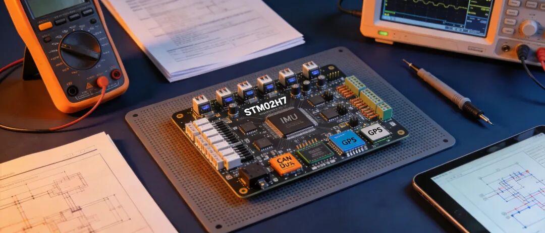
Opening: One Board Killed Three Months of Progress
Last autumn, a surveying drone team stepped into a classic trap.
Their technical lead selected a well-regarded open-source flight controller board with an active community following. STM32F4 main chip, dual IMU redundancy, a full set of interfaces, and mountains of community documentation. It passed the selection review unanimously: great value, active community, and easy to hire engineers who know the platform.
The board arrived, firmware was flashed, and the drone flew. Everything worked perfectly in the lab.
The problem appeared during field trials.
First flight: 38°C ambient temperature. After 15 minutes, IMU bias drift became uncontrollable. The compensation possible at the algorithm level could no longer cover the drift at the hardware level. Attitude estimation began to jitter, the flight path started to veer, and the ground station flooded with warnings. The pilot switched to manual control and landed safely.
Back in the lab, the data told the story: the IMU’s temperature drift curve showed a nonlinear jump above 35°C. This IMU’s drift specification was rated at 25°C — its behavior in high-temperature operation had never been validated. Consumer-grade IMU chips look great on paper, but their performance outside the industrial temperature range is simply not documented.
So they swapped in an industrial-grade IMU. Then came recalibration, retuning, and re-running field validation. Three weeks of effort, gone.
Second flight: temperatures had dropped and the IMU was fine. But the barometer showed severe pressure drift at high temperature — altitude-hold accuracy degraded from ±0.5m to ±3m. Surveying missions demand tight altitude precision, and this error was unacceptable. Another two weeks of troubleshooting and replacement.
Third flight: barometer and IMU were stable. But the CAN bus started dropping frames under high temperature and heavy vibration. After investigation, the CAN transceiver selection was fine — the problem was board layout. The CAN traces ran too close to the motor-driver traces, and EMI crosstalk amplified at high temperature. This was not a problem a chip swap could solve; the PCB layout had to change. Redesigning the PCB means re-fabbing, re-assembly, and full revalidation.
Three months, three rounds of rework. The few thousand yuan saved on board cost did not even cover a fraction of the labor spent.
What is the real lesson here? The team selected based on spec sheets and price alone, without looking at engineering depth at the hardware-design level. MCU model, IMU chip, sensor precision — these are the “visible parameters.” Temperature-drift compensation curves, PCB layout isolation, power-supply ripple suppression, EMI protection — these are the “invisible engineering.”
Visible parameters determine whether a flight controller can fly. Invisible engineering determines whether it can fly reliably in real operating conditions.
This guide breaks down the seven most critical dimensions of open-source flight controller hardware selection. Every dimension is a pitfall dug out of real projects, and every pitfall comes with an engineering-level avoidance path. The target readers are frontline flight controller engineers and technical leads at OEMs — what you need to look at during selection goes far beyond the spec sheet.

MCU Selection: More Compute Is Not Always Better, But Running Out Is Fatal
The MCU is the brain of the flight controller. The first thing everyone checks is clock speed — higher frequency, more compute, more complex algorithms. That logic is not wrong, but it is incomplete.
MCU selection must consider five dimensions: clock speed and compute power, floating-point unit (FPU), memory capacity and type, peripheral interface count and specifications, and power consumption and thermal design.
The STM32H7 is the current mainstream choice for industrial-grade open-source flight controllers. 480MHz clock, double-precision FPU, 1MB Flash + 1MB RAM (H743), and rich peripherals (up to 6 UARTs, 4 SPIs, 3 I2Cs, 2 CAN FD, multiple ADC/DAC channels). PX4 and ArduPilot’s primary supported platforms are both H7 series. From an ecosystem-compatibility standpoint, H7 is the safest choice today.
But “mainstream” does not mean “universal.” Before choosing an MCU, clarify exactly which algorithms you intend to run:
- How heavy is the EKF state estimator? An EKF with 15+ states needs double-precision floating point from the FPU; the H7’s double-precision FPU can complete it in under 1ms. If you use an F4 (single-precision FPU), you must convert the EKF to single precision. The accuracy loss is within acceptable range, but it requires additional precision validation.
- Will optical flow / visual odometry run on the main chip? If yes, the H7’s compute is barely sufficient, but memory may become tight. Running flight controller firmware + EKF + visual odometry in 1MB RAM leaves little headroom. At that point you either move to the H750 (external SDRAM interface) or offload vision algorithms to a co-processor.
- Will you run communication protocol stacks on the main chip (MAVLink, ROS2 DDS)? MAVLink overhead is modest; ROS2 DDS overhead is not. If you plan to run full ROS2 nodes on the MCU, we recommend at least 2MB RAM — or go straight to a dual-chip architecture: flight controller MCU + mission computer.
A common mistake: selecting by compute in reverse. “H7 has the most compute, so pick H7.” The problem with this logic is that unused compute is simply wasted power and heat. A flight controller doing only attitude control + GPS navigation is more than served by the F4. Moving to H7 just adds a thermal problem you now have to solve.
Well-designed boards tier their MCU selection by compute class: entry tier uses the F4 (lightweight applications), standard tier uses the H7 (industrial applications), advanced tier uses H7 + co-processor (vision/AI applications). Match your actual requirements to the right compute class instead of blindly buying the top configuration.
On power: the H7 consumes roughly 0.5–0.8W at full load. That number looks small, but inside a sealed enclosure at high ambient temperature, 0.8W of heat has nowhere to go. Board temperature climbs from 40°C to 60°C+, which in turn degrades the accuracy of the IMU and other temperature-sensitive components. Industrial-grade designs handle thermal paths explicitly — thermal vias, copper pours, even thermal pads bonded to the enclosure. None of this appears on a spec sheet, but in field trials it decides whether your flight controller degrades from overheating.
IMU Configuration: The Industrial vs. Consumer Gap Lives in the Temperature Curve
The IMU (inertial measurement unit) is the flight controller’s core sensor. Its precision and stability directly determine attitude estimation quality.
IMU chips commonly used in the open-source flight controller community fall into three tiers:
Consumer grade: ICM-42688P, BMI270, and similar. Gyro bias stability on the order of ±1°/s, accelerometer bias stability on the order of ±10mg. Low unit price — tens of yuan. Toy drones and FPV racing quads are perfectly served by these. Industrial applications, however, are not.
Industrial grade: ICM-45686, ADIS16470, STIM300, and similar. Gyro bias stability from ±0.3°/s down to ±0.01°/s, accelerometer bias stability from ±1mg down to ±0.1mg. Unit prices range from a few hundred to a few thousand yuan.
Tactical grade: ADIS16490, HG4930, and similar. Gyro bias stability better than 0.001°/s, accelerometer bias stability better than 0.01mg. Unit prices run from tens of thousands upward. Military and aviation navigation grade.
The vast majority of industrial drones (surveying, inspection, agriculture, logistics) use industrial-grade IMUs. Consumer-grade IMU precision is fine in the lab, but it falls apart in the field. Why? Temperature.
Consumer IMUs typically specify an operating temperature range of -40°C to +85°C, but precision is only rated at 25°C. The further the temperature drifts from 25°C, the larger the bias drift — and the drift curve is nonlinear. Industrial IMUs rate their precision across the full temperature range, are calibrated over the full range at the factory, and ship with individual temperature-drift compensation parameters per chip.
That is exactly the trap the surveying team fell into: consumer IMU bias drift at 38°C far exceeded expectations, because the drift data at that temperature point simply is not in the datasheet.
Industrial-grade open-source flight controllers follow several IMU selection principles:
First, use full-temperature-range calibrated industrial chips, not consumer chips calibrated only at room temperature. The unit price is several times higher, but it eliminates the cost of repeated recalibration and repeated crash-and-rebuild cycles during field trials.
Second, build in redundancy. Dual IMUs are the minimum requirement — primary IMU + backup IMU, two independent measurement paths with cross-validation. If the primary IMU reading goes abnormal (deviation from backup exceeds threshold), switch to backup immediately. Triple IMU is even better: two-out-of-three voting provides stronger fault tolerance.
Third, IMU mounting must include vibration isolation. MEMS IMUs are vibration-sensitive; high-frequency vibration couples into accelerometer readings as high-frequency noise. Well-designed boards add damping structures around the IMU pads — either damping pads, mounting the IMU at the PCB’s vibration node (center of the board, near mounting holes), or silicone vibration isolators. These mechanical design details determine the IMU’s effective precision in real vibration environments.

Sensor Redundancy: Barometer, Compass, and GPS Fault-Tolerant Design
The IMU is the core of attitude estimation, but a flight controller is not just an IMU. The barometer provides the altitude reference, the magnetometer provides the heading reference, and GPS provides position and velocity references. If any single sensor fails, attitude/navigation estimation is compromised. Redundancy is not optional — it is a baseline requirement for industrial-grade flight controllers.
Barometer redundancy
The barometer measures atmospheric pressure and converts it to altitude. Accuracy is affected by temperature, humidity, and airflow. Single-barometer altitude-hold accuracy is typically around ±0.5m.
Redundancy strategy: dual barometers, physically separated. Why separated? Because two barometers placed close together sense the same local airflow disturbance (e.g., propeller downwash), and the common-mode error cannot be eliminated by cross-validation. Well-designed boards place the two barometers at opposite ends of the PCB, or mount one on the board and route the other via an external tube to another position on the airframe.
Failover logic: in normal operation, the two barometer readings are combined with a weighted average (weights dynamically adjusted by each sensor’s historical variance). If one reading jumps abnormally (deviation from the other exceeds threshold), the abnormal one is discarded and the healthy one is used. If both are abnormal (e.g., severe airflow turbulence in strong wind), fall back to pure inertial altitude estimation (accelerometer integration) — accuracy drops, but control is never lost.
Compass redundancy
The magnetometer measures the Earth’s magnetic field direction to provide heading. Its biggest problem is magnetic interference — motors, ESCs, power cables, and carbon-fiber airframe all generate magnetic fields that corrupt compass readings.
Redundancy strategy: dual compass + external compass. The onboard compass sits on the flight controller board and is heavily exposed to the board’s own electromagnetic interference. An external compass is mounted on a mast extending outside the airframe, away from interference sources. Dual compasses cross-validate; onboard is primary and external is secondary (external usually has higher precision but constrained mounting).
Fault detection: the most common compass failure modes are “soft-iron interference” and “hard-iron interference.” Soft-iron is heading-dependent interference from magnetic materials in the airframe; hard-iron is a constant magnetic offset. Both can be compensated by calibration, but compensation parameters drift over time. Flight controller firmware should include online compass health checks — compare compass heading against GPS heading (derived from the GPS velocity vector); if the deviation exceeds threshold, raise an alarm.
GPS redundancy
GPS provides position, velocity, and time. Single-GPS positioning accuracy is 2–5m (RTK reaches centimeter level), velocity accuracy 0.1m/s.
Redundancy strategy: dual GPS receivers. Primary GPS + backup GPS with two independent antennas and receivers. Failover is similar to the IMU — cross-validation, switch to backup when deviation exceeds threshold.
One easily overlooked detail: the two GPS antennas must be separated by adequate distance (at least 30cm). Otherwise both antennas experience the same multipath effects and blockage, and the common-mode fault cannot be eliminated by redundancy. Well-designed boards reserve two GPS interface ports at the connector level, with identical interface specifications (both UAVCAN or both UART) for easy adaptation to different GPS receiver models.
The core principle of redundancy: heterogeneous redundancy > homogeneous redundancy. Homogeneous redundancy (two identical sensors) handles random faults (one chip fails), but not common-mode faults (temperature, vibration, and EMI affect both chips identically). Heterogeneous redundancy (sensors of different types and principles) handles common-mode faults. For altitude estimation, for example, barometer + accelerometer integration + laser rangefinder — three different measurement principles — means no single failure can completely eliminate altitude estimation.
Industrial-grade open-source flight controllers design redundancy at the system level — not just adding more chips, but systematically addressing sensor layout, fault-detection algorithms, and failover logic. When evaluating redundancy, do not just count chips; check whether the layout is sound and whether the failover logic is complete.
Interfaces & Protocols: MAVLink, CAN, and Serial Selection Decisions
Interfaces are the flight controller’s bridge to the outside world. Choose wrong, and the adaptation work that follows can sink the entire project.
MAVLink version
MAVLink is the most universal communication protocol in the drone industry. The mainstream versions are v1 and v2. v2 is a superset of v1 — more message types, message signing (anti-spoofing), and a larger ID space.
Selection principle: only choose flight controllers with MAVLink v2 support. v1 has stopped evolving; all new features land on v2. If your flight controller only supports v1, you cannot use v2’s new message types or message signing (which is a hard requirement in anti-GPS-spoofing scenarios).
PX4 and ArduPilot both fully support MAVLink v2. But some early open-source boards with constrained serial resources may default to v1 in firmware configuration. Check the firmware config during selection to confirm v2 runs.
CAN bus
The CAN bus is increasingly important in industrial drones. PX4’s DroneCAN (formerly UAVCAN v0) and the newer UAVCAN v1 both run on CAN. CAN advantages: multi-node, high real-time performance, strong noise immunity, simple wiring (twisted pair).
Typical applications: CAN connects ESCs, GPS receivers, barometer modules, pitot tubes, and battery management modules (BMS). Dozens of nodes can hang off a single CAN bus, each with its own address, communicating without collisions.
Check the CAN controller specification during selection. The STM32H7 has two CAN FD (Flexible Data-rate) channels at up to 8Mbps each. CAN FD is the evolution of classic CAN: single-frame payload grows from 8 bytes to 64 bytes for higher efficiency. Well-designed boards bring out both CAN FD channels — one for DroneCAN peripherals, one for redundant communication or custom protocols.
A classic pitfall: CAN transceiver selection. The CAN controller’s signals need a transceiver to convert to differential signals. The transceiver’s speed, drive capability, and ESD protection level must match. Some low-cost open-source boards skimp on the transceiver, choosing low-speed parts that drop frames on long runs (over 2m) or under heavy vibration. During selection, confirm the CAN transceiver is a high-speed part (e.g., TJA1044, MCP2562) with proper ESD protection.
Serial ports and I2C/SPI
Serial (UART) is the flight controller’s most basic interface. GPS, telemetry radios, and payload devices all communicate over serial.
During selection, count how many serial ports you need: GPS 1–2, telemetry 1, telemetry downlink 1, payload 1–2, debug 1. That adds up to 5–7. The STM32H7 has 6–8 UARTs, enough in quantity. But verify every channel is actually broken out to headers or connectors, not just test points.
I2C and SPI are typically used for onboard sensors. I2C is slow (400kHz standard mode), suited to low-speed sensors (barometer, compass). SPI is fast (tens of MHz), suited to high-speed sensors (IMU). What matters at selection time: how many devices hang on the I2C bus, whether bus capacitance is exceeded, and whether SPI trace lengths are controlled. These are PCB-layout concerns, but the selection stage is when you check whether the board designer addressed them.
Industrial-grade open-source flight controllers share two interface-planning traits: critical interfaces are redundant (dual CAN, dual GPS serial) and interface protection is in place (TVS diodes for surge, opto-isolation for ground loops, filters for EMI). During selection, open the board schematic or interface documentation and check whether protection circuits exist. Unprotected interfaces work fine in the lab — then burn up in the field.
Power Design: Redundant Supply and Voltage Monitoring Engineering Details
Power is the flight controller’s lifeline. If power fails, the flight controller powers off instantly and the aircraft drops. This is not a “performance issue” — it is a “safety issue.”
Redundant power supply
Industrial-grade flight controllers should implement at minimum dual power feeds: primary power (traction battery stepped down via BEC/PDB) + backup power (independent battery or independent BEC). When primary power fails, the backup takes over seamlessly and the flight controller never loses power.
“Seamless” is the key. Switch time must be millisecond-level — the flight controller’s power-loss detection window is typically 10–50ms; beyond that, the controller assumes power loss and triggers emergency procedures. Ideally, switch time is under 1ms. The usual implementation is OR-ing diodes or ideal diode controllers — both feeds supply simultaneously, the higher-voltage rail wins, and the lower one is isolated. When the primary rail sags, the backup takes over automatically with zero switching delay.
Well-designed boards add reverse-polarity protection (P-MOSFET), overvoltage protection (TVS for surges), and overcurrent protection (resettable fuses) at the power entry. These protection circuits must respond in microseconds; otherwise a surge destroys downstream chips before the fuse even trips.
Voltage monitoring
The flight controller must monitor input voltage and each power rail in real time, for two reasons: low-voltage alarms (battery nearly empty — prompt the pilot to return) and power-health detection (an abnormal rail voltage triggers early warning).
Voltage-monitoring ADC channels need adequate precision and sample rate. Voltage measurement accuracy should be at least ±1%, sample rate at least 1kHz (to catch transient voltage sags). Some low-cost boards use low-precision ADCs or insufficient divider resistors, producing badly skewed voltage readings. Skewed readings mean inaccurate low-voltage alarm thresholds — either alarming at 20% battery (wasted flight time) or staying silent at 5% (dangerous).
Current measurement
Current measurement monitors the propulsion system’s operating state. Current data reveals motor stalls, ESC anomalies, and overload conditions. Industrial flight controllers typically place a current sensor (Hall sensor or shunt) at the power input to measure total current in real time.
Current sensor selection criteria: range (cover maximum operating current plus margin), accuracy (at least ±2%), bandwidth (at least 1kHz, to catch transient current changes), and isolation (galvanic isolation between high power and low power to prevent noise coupling into sensitive flight controller circuits).
The core principle of power design: over-design rather than just-enough. Keep at least 30% power margin. A BEC rated at 5A should not see real load above 3.5A. For 12V/5V outputs, keep ripple within 50mV. These margins look wasteful in the lab, but in the field — at high temperature, under vibration — they are the difference between life and death.
Expansion Capability: Reserved Interfaces Decide How Far You Can Go
Flight controller selection is not just about today’s requirements. Products iterate, requirements change, customers raise new demands. A board’s expansion capability determines whether you can avoid changing platforms for the next 1–2 years.
Reserved interfaces
The most basic expansion capability: spare serial ports, spare CAN channels, free ADC channels, reusable GPIOs.
A typical scenario: in the product’s second year, a customer asks to add a LiDAR for obstacle avoidance. The LiDAR needs one serial port (or CAN) and one GPIO (for sync trigger). If the flight controller’s interfaces are already occupied by GPS, telemetry, downlink, and payload, what do you do? Either swap to a board with more interfaces (firmware migration) or add a serial-expansion chip (hardware modification). Both cost time, and hardware changes during mass production cost far more than during prototyping.
Inventory your interface usage during selection and reserve at least 20% headroom. If you need 5 serial ports, choose a board with 7+. If you need 1 CAN, choose a board with 2.
Modular design
A better expansion approach is modularity. Core board + carrier board architecture: the core board integrates the MCU, IMU, power, and other critical components; the carrier board handles interface breakout and peripheral circuits. To add features later, swap the carrier board — the core board stays untouched.
This architecture’s benefits: the core board is fully validated (EMC, vibration, temperature) and reusable; carrier boards are customized per requirement without affecting the core board. Iteration is faster and validation costs are lower.
If an industrial-grade open-source flight controller offers modular architecture, prioritize it during selection. Core/carrier separation means future upgrades do not require revalidating the entire controller — the core board stays the same, firmware untouched, only the carrier board changes.
Co-processor interface
If you foresee running vision algorithms or AI models, check for co-processor interfaces during selection. A common setup: the flight controller MCU connects via SPI or UART to a co-processor (e.g., Jetson Nano, Raspberry Pi CM4, Kendryte K210). The co-processor runs compute-heavy algorithms (visual odometry, object recognition, path planning) while the flight controller MCU focuses on real-time control.
Co-processor interface design must address data bandwidth and latency. Vision algorithms need to move image or feature data — high bandwidth (SPI at least 20MHz, or PCIe). Real-time control needs low latency (10ms control loop; data transfer latency must stay under 1ms). Confirm the co-processor interface specification can satisfy future requirements during selection.

Closing: The Core Principles of Hardware Selection
Return to the surveying drone team’s lesson from the opening. Three months, three rounds of rework, labor plus materials — far exceeding the money saved on board unit price.
The core principle of hardware selection boils down to one sentence: the balance point among performance, reliability, expandability, and cost lives not in the spec sheet, but in your product requirements.
Performance is the entry ticket — is the MCU compute sufficient, is the IMU precision sufficient, is the interface count sufficient. These are the basics; fail them and you are out. But there is a line between sufficient performance and surplus performance; crossing it is waste.
Reliability is the moat — temperature tolerance, vibration tolerance, EMC, power redundancy. None of this is written in the spec sheet or raised at the selection review, but it recurs in field trials and customer complaints. Well-designed boards invest far more in reliability than in raw performance. What you need to evaluate is not whether the board can fly, but whether it can fly stably under real operating conditions.
Expandability is the insurance — reserved interfaces, modular design, co-processor support. You may not need it today, but six months from now when the customer raises a new requirement, you will thank yourself for that extra glance during selection.
Cost is a constraint — not the only one, but a real one. Board unit price matters, but total cost of ownership matters more: rework cost, labor cost, downtime cost, iteration cost. A board that costs 30% more but is better designed can have 50% lower total cost of ownership than a cheap board that requires endless rework.
During selection, look at three extra things: the schematic (are protection circuits present, is redundancy designed in), the layout (IMU position, interface spacing, thermal paths), and the temperature test report (is full-temperature-range performance validated). These three are not in the spec sheet, but they determine the board’s engineering depth.
Industrial-grade open-source flight controllers are supported by engineering discipline at every stage — from chip selection to PCB layout to power design to redundancy architecture. These disciplines are not numbers in a datasheet; they are experience distilled from countless projects that paid tuition in the field. Spend one extra look at engineering details during selection, and you save one middle-of-the-night phone call during mass production.
In the next article, we will discuss another critical dimension of open-source flight controller firmware selection — operating systems and middleware. The water runs deep there; we will take it slowly.
Key Takeaways
- Match MCU compute class to actual algorithms (STM32H7 for industrial, F4 for lightweight); surplus compute is just wasted heat.
- Industrial IMUs are calibrated across the full temperature range; consumer IMUs are only rated at 25°C and drift nonlinearly in the field.
- Sensor redundancy must be heterogeneous — barometer + inertial + rangefinder beats two identical sensors for common-mode faults.
- Require MAVLink v2, high-speed CAN transceivers, and protected interfaces (TVS, opto-isolation) as non-negotiables.
- Dual power feeds with sub-millisecond OR-ing failover, ±1% voltage monitoring, and 30% power margin are industrial baseline.
- Reserve at least 20% interface headroom; prefer modular core+carrier architectures for future expansion.
Have questions about this article? Feel free to contact us at [email protected] — we’re happy to help!
Frequently Asked Questions
Q: Is the STM32H7 always the right MCU choice for open-source flight controllers?
Not always. H7 is the safest ecosystem choice (PX4/ArduPilot), but if your workload is only attitude control + GPS navigation, an F4-class MCU is sufficient and avoids unnecessary heat. Select by compute class matched to your algorithms, not by peak specs.
Q: Why do consumer IMUs fail in industrial drones despite good datasheet specs?
Consumer IMUs rate precision only at 25°C. Outside that temperature, bias drift grows nonlinearly, and the drift curves are not documented. Industrial IMUs are factory-calibrated across the full temperature range with per-chip compensation parameters.
Q: What is the difference between homogeneous and heterogeneous redundancy?
Homogeneous redundancy (two identical sensors) survives random component failure but not common-mode faults (temperature, vibration, EMI affect both equally). Heterogeneous redundancy (different sensor principles, e.g., barometer + inertial + LiDAR for altitude) survives both.
Q: Why does MAVLink v2 matter for flight controller selection?
MAVLink v1 is no longer evolving. v2 adds new message types and message signing, which is essential for anti-GPS-spoofing and secure telemetry. Some early boards default to v1 in firmware — verify v2 support before selecting.
Q: How much interface headroom should I reserve when selecting a flight controller?
At least 20%. If you need 5 serial ports today, choose a board with 7+. Products evolve — adding LiDAR, extra payloads, or new telemetry later is far cheaper with spare interfaces than with a platform swap during mass production.
If you have any questions about this topic, feel free to contact us at [email protected]

Pingback: Flight Controller Selection: 5 Parameters Behind Mass-Production Success (2026) – AOMWAY