Key Takeaways
- ArduPilot’s firmware exceeds 700,000 lines of code; pymavlink lets you build UAV features without reading a single line of it.
- A WFG120A flight controller running ArduCopter 4.6.3 talks to a Raspberry Pi 4B over MAVLink 2 at 921600 baud.
- Pick an idle serial port (Serial7/UART7 in this build) and leave Serial3 GPS, Serial4 telemetry and Serial6 RC_IN alone.
- UART wiring is crossover with a common ground, and the Raspberry Pi must be powered from its own 5V supply.
- pymavlink turns raw MAVLink packets into Python objects, so AI detection and guidance logic runs outside the flight controller firmware.
pymavlink is the fastest way into ArduPilot secondary development for UAV teams: instead of reading the flight controller’s 700,000+ lines of firmware, you attach a Raspberry Pi as a companion computer and speak MAVLink 2 to the autopilot over a serial link. As of 2026, this is the standard architecture for adding AI recognition, autonomous guidance or custom mission logic without touching — or risking — the certified flight-critical code.
Why pymavlink Beats Reading ArduPilot Source Code
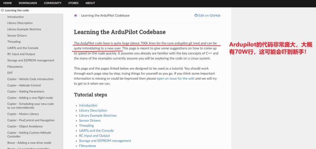
Do you really need to grind through the ArduPilot source tree to start secondary development? ArduPilot’s own learning material is honest about the scale: the codebase runs past 700,000 lines, which is an easy route from “getting started” to “giving up”. A far gentler entry point is pymavlink.
The approach in this guide uses an Aomway WFG120A flight controller as the example platform. The idea is simple: leave the flight controller’s core code untouched, hang a Raspberry Pi (or any Linux compute board) off one of its serial ports, then do your business logic in Python on the Pi. pymavlink carries the MAVLink conversation between the two. That is how you bolt on AI recognition or autonomous guidance — capabilities the stock firmware has never had — while keeping the risk of a bad edit far away from the flight-critical code.

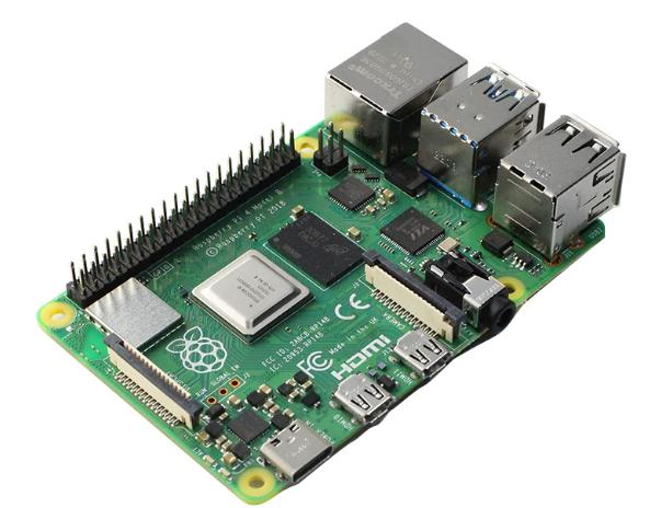
Companion computers are usually Linux boards: Raspberry Pi, Orange Pi or Rockchip-class compute modules. They all work much the same way. The Raspberry Pi 4B is the most common entry-level choice — ArduPilot’s official source even ships adaptations for it — and its tutorials are plentiful and its OS install is trivial. This build uses a spare Raspberry Pi 4B.
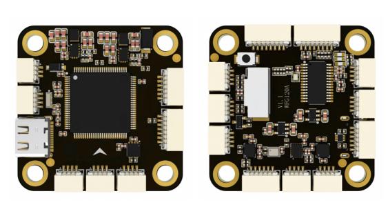
The flight controller side of the bench is an Aomway WFG120A.
ArduPilot Serial Port Mapping, Explained
Serial wiring and configuration is where most beginners trip. Every flight controller vendor exposes serial ports directly, but you have to understand how ArduPilot’s logical Serial ports map onto the microcontroller’s physical USARTs, and what each one is configured for by default. Vendors normally publish a mapping table. Here is the mapping for the WFG120A:
| ArduPilot Serial | Default Function | MCU UART | Connector |
|---|---|---|---|
| Serial1 | None (empty) | USART1 | Standalone 4-pin SH1.0 socket |
| Serial2 | None (empty) | USART2 | On the HD video-link connector |
| Serial3 | GPS | USART3 | On the GPS & compass connector |
| Serial4 | Mavlink2 (telemetry radio) | UART4 | Standalone 4-pin SH1.0 socket |
| Serial5 | None (empty) | UART5 | Standalone 4-pin SH1.0 socket |
| Serial6 | RC_IN (receiver input) | USART6 | On the RC receiver connector |
| Serial7 | None (empty) | UART7 | Standalone 4-pin SH1.0 socket |
| Serial8 | None (empty) | UART8 | Standalone 4-pin SH1.0 socket |
Mapping tables differ between vendors, so always check the manual that ships with your board. So which port should feed the Raspberry Pi?
- Serial4 (UART4) — already assigned to Mavlink2 for the wireless telemetry radio.
- Serial6 (USART6) — RC_IN for the receiver; don’t touch it.
- Serial3 (USART3) — GPS by default; don’t take it either.
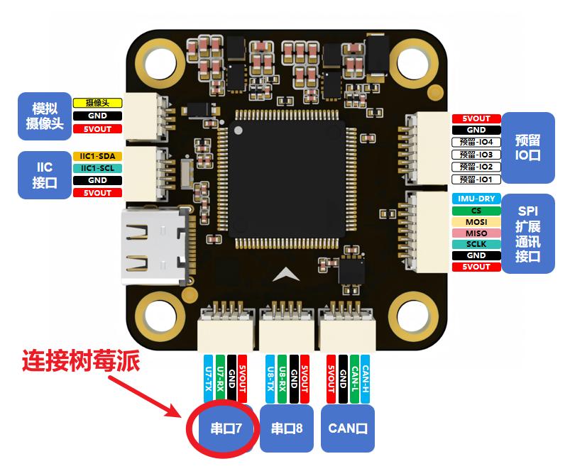
With those three excluded, any other idle serial port can be defined freely. This build uses Serial7 (UART7) on the WFG120A to talk to the Raspberry Pi.
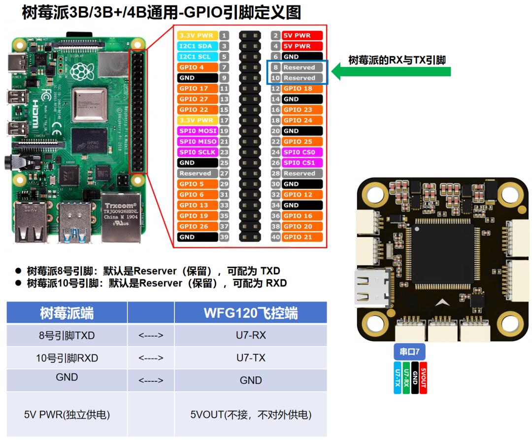
Wiring the WFG120A to a Raspberry Pi 4B
Connect WFG120A Serial7 (UART7) to the Raspberry Pi 4B hardware UART (GPIO8 and GPIO10). Remember that UART wiring is crossover (TX to RX, RX to TX), the grounds must be commoned, and the Raspberry Pi needs its own 5V supply — do not try to power it from the flight controller.
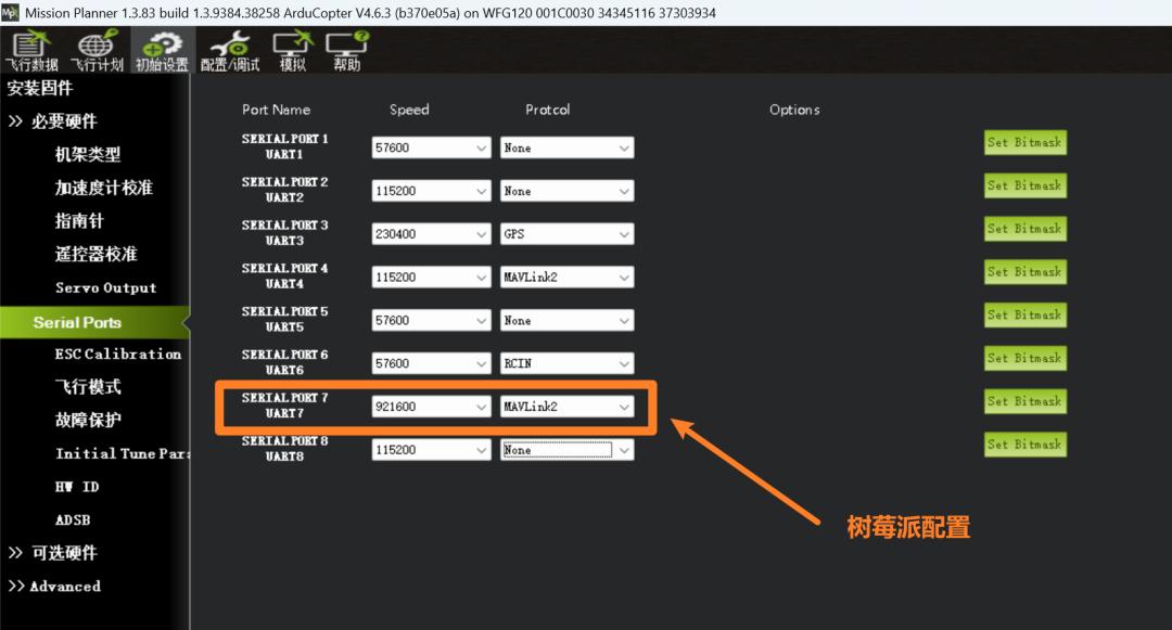
Configuring the Serial Function and Baud Rate
Baud rate matters. With ArduCopter 4.6.3 firmware and Mission Planner 1.3.83, the link will not come up out of the box: Serial7 defaults to no function. Connect the WFG120A to a PC over USB, then in Mission Planner go to Initial Setup → Mandatory Hardware → Serial Ports and configure:
- Serial baud rate: 921600
- Serial function: Mavlink2
Installing Raspberry Pi OS
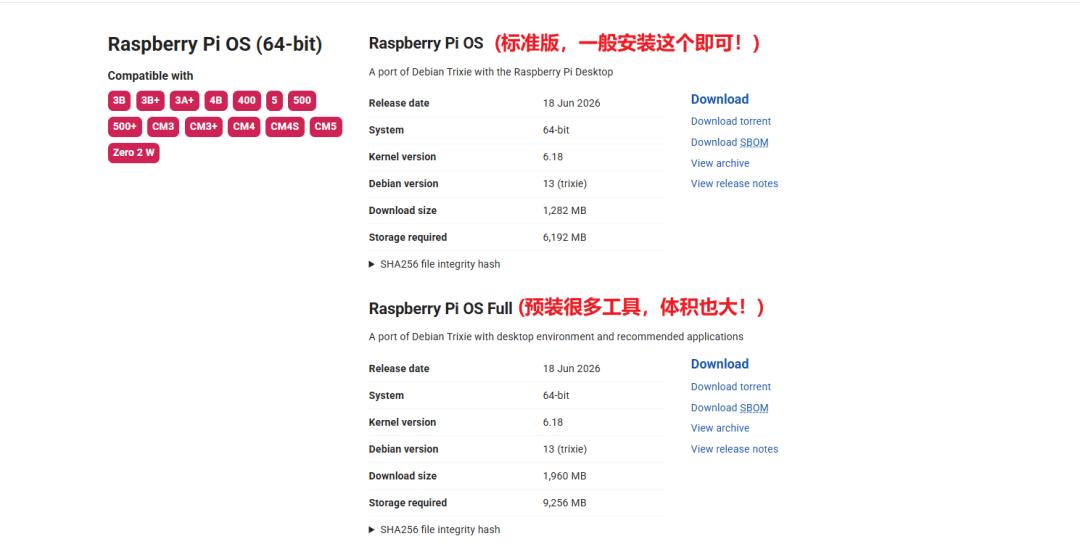
Download Raspberry Pi OS (Legacy, 64-bit) from the official site and flash it to an SD card with Raspberry Pi Imager — 32GB or larger is recommended, and the card should be formatted FAT32 first. Then walk through the usual OS install and account setup; the documentation and video guides for this are excellent, so there is no need to repeat them here.
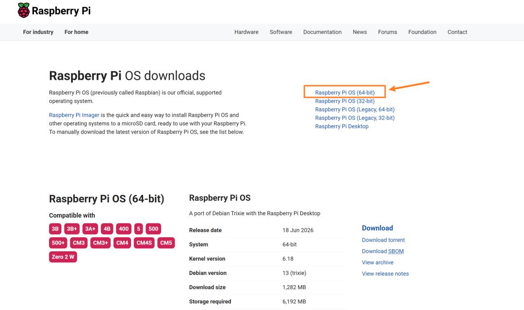
Note that the download page offers both Raspberry Pi OS and Raspberry Pi OS Full. The Full image preinstalls every recommended package — a large set of programming tools such as Thonny, Mu and Geany, mathematics software, even retro game emulators. Most users will never touch them, so the standard image is the better choice here.
Enabling the Raspberry Pi Serial Port with raspi-config
Once the OS is installed, hook the Pi up to a monitor over HDMI plus a mouse and keyboard, and it behaves like any desktop. The first job is enabling the serial port. Open a terminal and run:
sudo raspi-config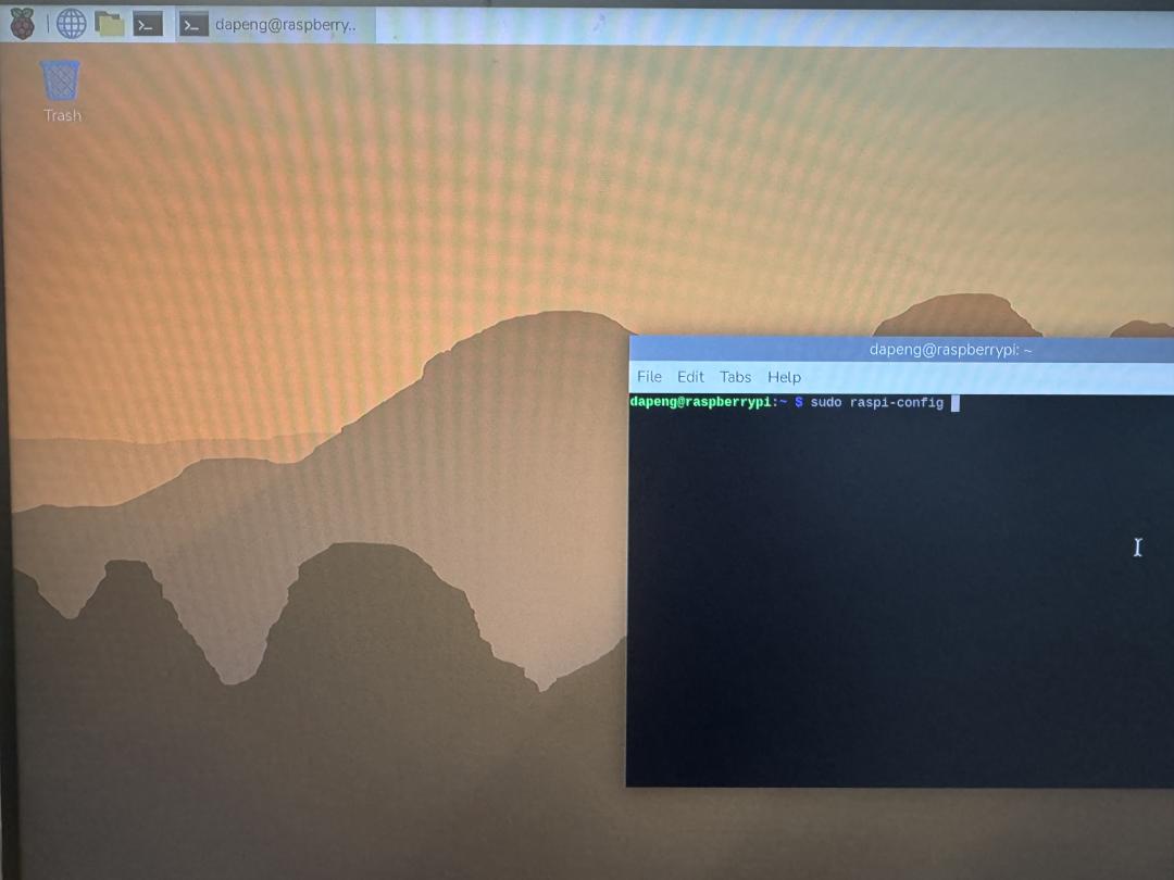
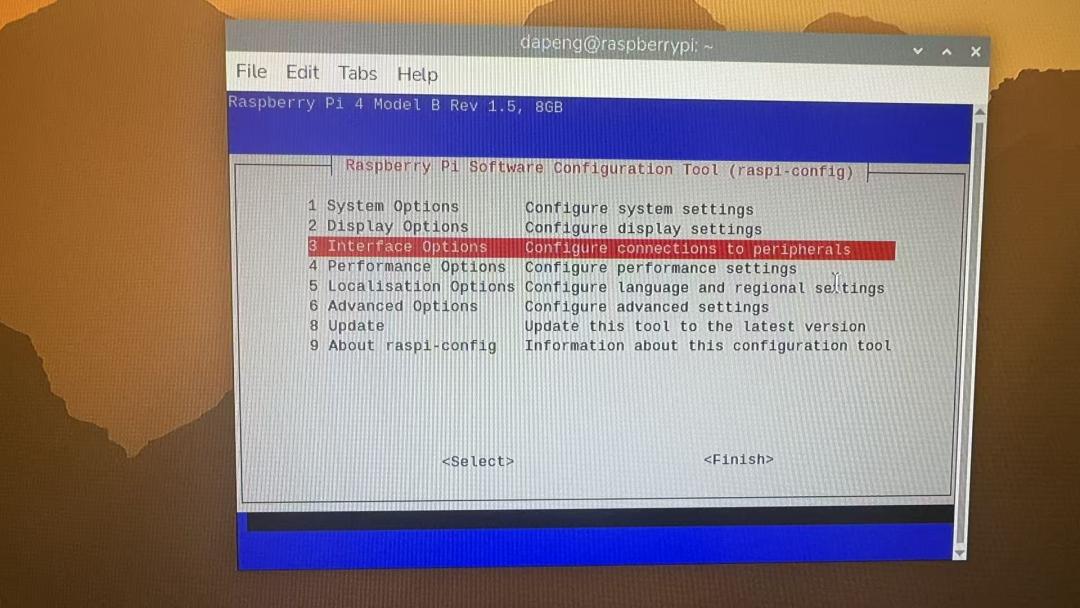
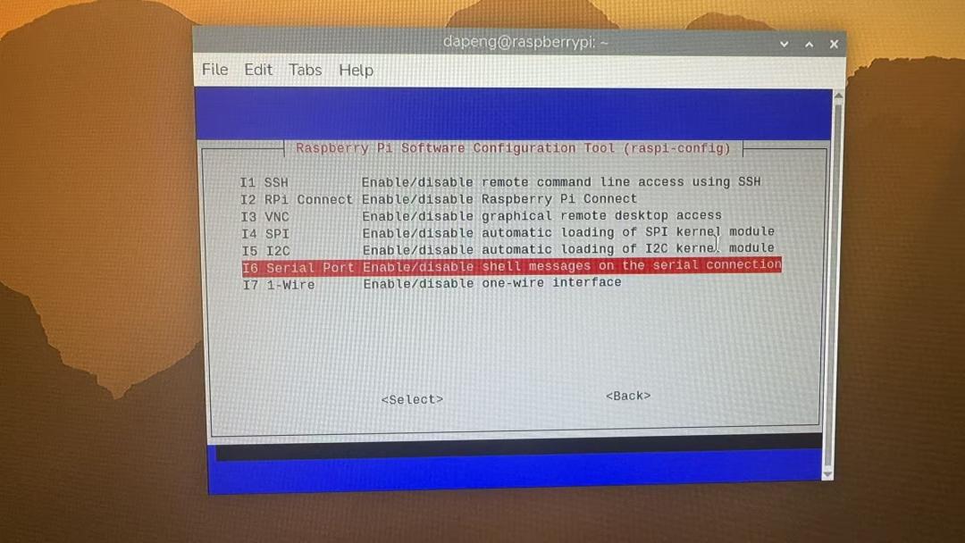
Then follow the on-screen sequence:
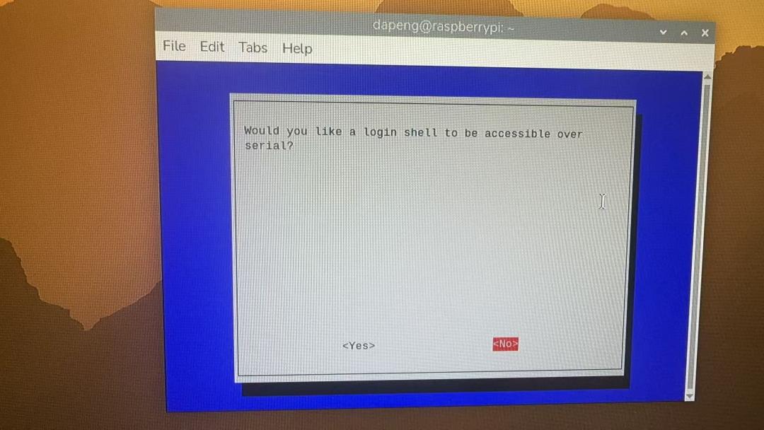
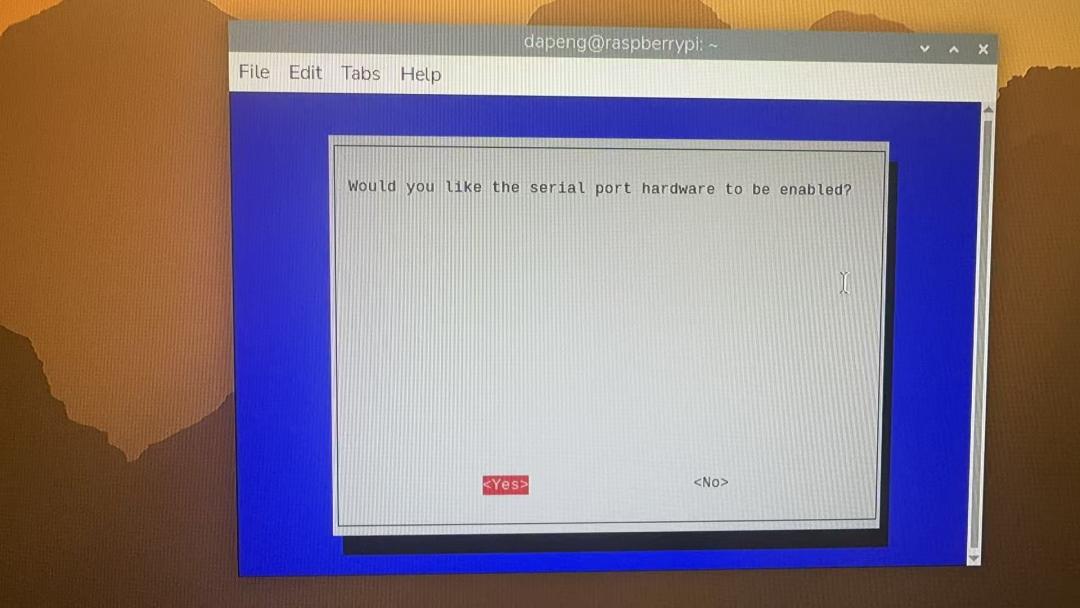
What Is pymavlink and How Do You Install It?
At this point the wiring, the flight-controller serial configuration and the Raspberry Pi serial configuration are all done. What remains is the software layer. ArduPilot firmware talks to the Raspberry Pi using the standard MAVLink 2 protocol. You don’t have to write the MAVLink code on the flight controller side — the open-source community already wrote it and it is integrated into the official firmware. The same is true on the Pi: installing the pymavlink library gives you flight-controller-to-Pi data communication without writing the protocol yourself.
pymavlink is the official Python library for accessing MAVLink. It parses the stream of binary messages the flight controller sends — attitude, position, battery, RC channels and so on — into Python objects, and it lets the Pi send commands back. Reading data and issuing commands both go through it.
Step 1: Check the Python and pip dependencies
Before installing pymavlink, confirm both dependencies are present:
python3 --version
python3 -m pip --version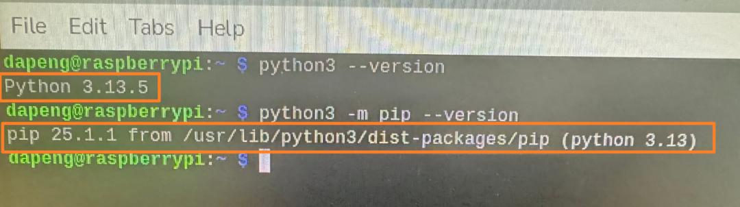
On a newer Raspberry Pi OS you install pymavlink inside a venv virtual environment; on older releases you can install it system-wide. The differences between versions are outside the scope of this guide.
Step 2: Create and activate a venv
cd ~
sudo apt install -y python3-venv
python3 -m venv ~/venv
source ~/venv/bin/activate
Once activated, the terminal prompt is prefixed with (venv), confirming you are inside the virtual environment.
Step 3: Install pymavlink
pip install pymavlink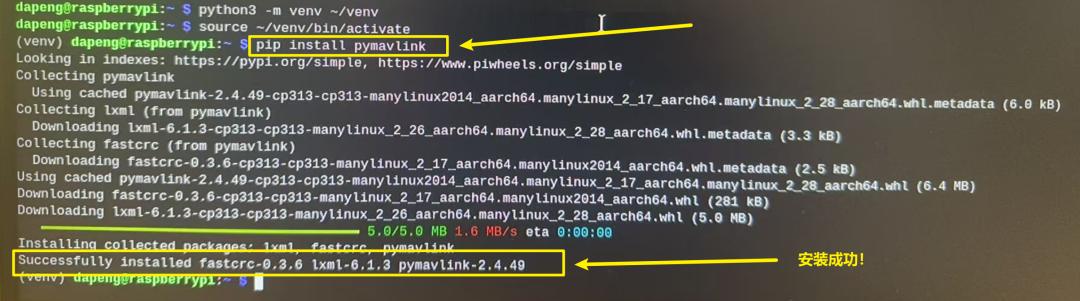
Don’t close the window. Closing the terminal exits the virtual environment — the (venv) prefix disappears — and your pymavlink programs will no longer run correctly.
Step 4: Reopen the terminal and reactivate
Whenever you open a new terminal, activate the environment first:
source ~/venv/bin/activate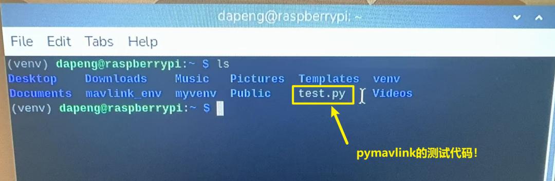
With (venv) back in front of the prompt you can run your scripts directly. An ls shows a test.py in the directory.
Step 5: Run test.py to verify the link
The test program is deliberately simple: if the Pi receives a heartbeat packet from the flight controller, it prints a short confirmation.
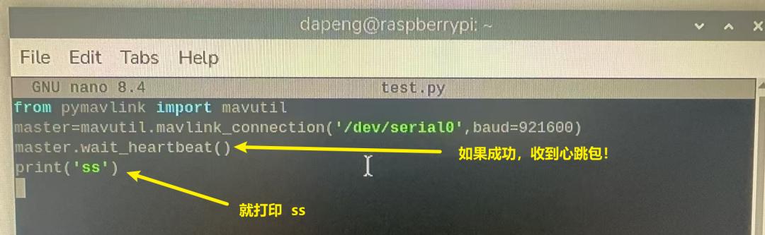
If the script throws an error, install the pyserial dependency and rerun:
pip install pyserial
python3 test.py
When the terminal prints the confirmation, MAVLink communication between the flight controller and the Raspberry Pi is working.
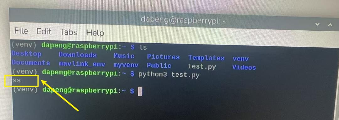
Example 1: Reading Flight Controller Attitude Angles
With pymavlink working, the next step is a small program that reads the flight controller’s attitude angles onto the Pi. Create test2.py:
# Prints flight controller yaw and pitch angles in real time
from pymavlink import mavutil
import math

# Connect to the flight controller over UART
master = mavutil.mavlink_connection('/dev/serial0', baud=921600)

# Wait for the heartbeat
master.wait_heartbeat()
print("Flight controller connected!")

# ================= Core code =================
# Ask the flight controller for the EXTRA1 stream (ATTITUDE) at 10 Hz
master.mav.request_data_stream_send(
    master.target_system,
    master.target_component,
    mavutil.mavlink.MAV_DATA_STREAM_EXTRA1,  # pitch, yaw, roll
    10,  # 10 Hz
    1    # 1 = enable
)
# ============================================

print("\nReading angles in real time! Press Ctrl+C to stop...")
try:
    while True:
        # Read ATTITUDE messages
        msg = master.recv_match(type='ATTITUDE', blocking=True, timeout=1)

        if msg:
            pitch = round(math.degrees(msg.pitch), 2)
            yaw = round(math.degrees(msg.yaw) % 360, 2)
            print(f"\rPitch: {pitch} deg   Yaw: {yaw} deg", end="", flush=True)

except KeyboardInterrupt:
    print("\nProgram exited!")
    master.close()
Run it with python3 test2.py, and the attitude angles stream live onto the Raspberry Pi terminal.
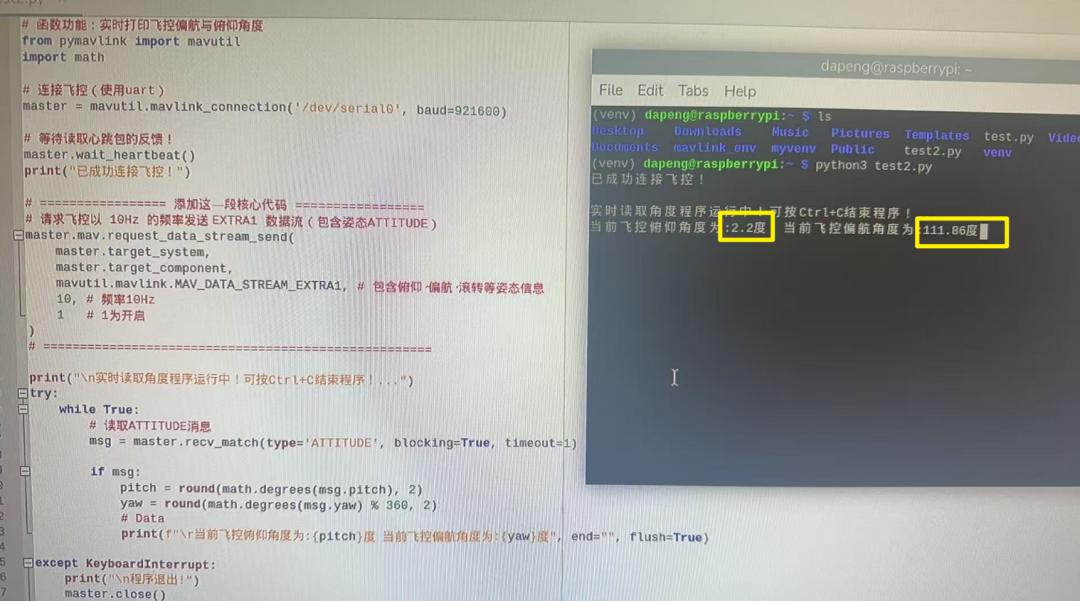
That is a milestone: you now have the pymavlink development pattern between a Raspberry Pi and ArduPilot under your belt.
Example 2: Three-Position Switch Conditional Logic
Here is a second example built around conditional logic. A very common requirement is using a transmitter’s position switch to trigger custom behaviour — run logic when the switch is low, drive a servo, or output a specific PWM value on a channel. In this demo the flight controller reads channel 6 live and prints whether the switch is in the low, middle or high position. Swap the business logic for your own and you have a working position-switch trigger.
#!/usr/bin/env python3
# Read RC_CHANNELS and classify channel 6 (3-position switch) by PWM
from pymavlink import mavutil
import time

# ===== 1) Connect to the flight controller (port and baud) =====
master = mavutil.mavlink_connection('/dev/serial0', baud=921600)
master.wait_heartbeat()
print("Connected, reading RC channel 6 (3-position switch)...")

# ===== 2) Request the RC channel stream (important!) =====
master.mav.request_data_stream_send(
    master.target_system,
    master.target_component,
    mavutil.mavlink.MAV_DATA_STREAM_RC_CHANNELS,
    10, 1
)

# ===== 3) Thresholds (dead zone widened so the middle position resolves) =====
PWM_LOW_MAX  = 1250   # below 1250 = LOW
PWM_MID_MIN  = 1250   # 1250-1750 = MID
PWM_MID_MAX  = 1750
PWM_HIGH_MIN = 1750   # above 1750 = HIGH

# ===== 4) Business function: put your own logic here =====
def on_switch(position):
    if position == 'LOW':
        print("Ch6 LOW (PWM < 1250) -> I am LOW")

    elif position == 'MID':
        print("Ch6 MID (PWM 1250-1750) -> I am MID")

    elif position == 'HIGH':
        print("Ch6 HIGH (PWM > 1750) -> I am HIGH")

# ===== 5) Main loop: keep reading the switch =====
last_pos = None        # remember the last position to avoid repeat prints

print("Waiting for RC data, flip channel 6 back and forth...")

try:
    while True:
        # Read the RC_CHANNELS message
        msg = master.recv_match(type='RC_CHANNELS', blocking=True, timeout=1)

        if not msg:
            continue

        # Read channel 6 correctly (chan6_raw, not channels[5])
        ch6 = msg.chan6_raw

        # [Debug] print the live PWM value so you can confirm it
        print(f"Ch6 live PWM: {ch6}    ", end="\r", flush=True)

        # Classify (three-way test avoids the dead zone entirely)
        if ch6 < PWM_LOW_MAX:
            pos = 'LOW'
        elif PWM_MID_MIN <= ch6 <= PWM_MID_MAX:
            pos = 'MID'
        elif ch6 > PWM_HIGH_MIN:
            pos = 'HIGH'
        else:
            pos = last_pos  # fall back to the previous state

        # Only act when the position actually changes
        if pos is not None and pos != last_pos:
            on_switch(pos)
            last_pos = pos

        time.sleep(0.05)

except KeyboardInterrupt:
    print("\nProgram exited!")
    master.close()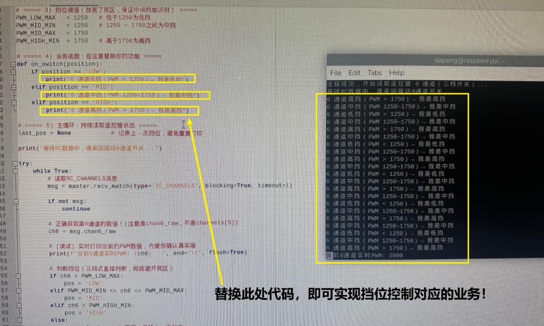
Replace the middle business logic and you have your own application: fire a manoeuvre when the barometer crosses a threshold, decide whether to release a payload based on sensor state, or enter guidance mode when an AI model’s confidence crosses a limit. This is the starting point for giving a drone intelligence through a Raspberry Pi.
Once that basic pattern is understood, implementing condition-driven behaviour becomes straightforward — even without deep knowledge of the flight controller’s own business code.
How to Auto-Start a Python Program on Boot
Why bother with autostart when you can run the script by hand? Picture the real scenario: the aircraft (or ground station) is powered up, and the Raspberry Pi should bring your program up by itself — detecting, boxing and guiding targets with nobody SSHing in to type a command. That is what onboard AI is supposed to look like: boot and run. If a human has to start it manually, it is no longer autonomous.
The most disciplined mechanism is a systemd service. Lighter options exist too — rc.local, a crontab @reboot entry, or a desktop autostart entry — each with its own trade-offs.

The homework for this one is to make a pymavlink program start automatically at boot, restart itself if it crashes, and write useful logs in the background. In the AI era this is easier than it sounds: describe the requirement to any AI assistant and it will hand you a complete, working systemd unit. Your job is to understand it and debug it as you deploy.
Where to Go Next
Once MAVLink is in hand, the scope expands quickly: reading attitude, position and mission state, writing your own ground station, running startup self-checks, logging data, multi-vehicle swarms and autonomous task scheduling. This is the dividing line between basic operation and flight-controller / ground-station / swarm development.

When you hit a specific problem, the pymavlink documentation and the official repository — message definitions and examples included — are the first place to look. You can also hand the requirement straight to an AI assistant and ask it to translate “I want the aircraft to do X by itself” into pymavlink set_mode, mission or command code; once the boundaries are familiar, progress is fast. For background on the protocol itself, see our MAVLink protocol complete guide, and if you would rather test logic before flying, our ArduPilot SITL simulation setup guide covers software-in-the-loop. It is also worth reviewing our ArduPilot parameter backup and restore checklist before flashing new firmware to a bench aircraft.
Aomway WFG120A Flight Controller Specifications
The WFG120A runs an STM32H743 main controller and supports four open-source firmware stacks: ArduPilot, PX4, Betaflight and INAV. It uses a dual-IMU design with an onboard QMC5883P compass, an external TF-card blackbox, and two onboard BECs (5V@3A and 12V@3A). Eight serial ports are broken out, so even after connecting a Raspberry Pi or AI compute board, a telemetry radio, two GPS modules, an RC receiver and an HD video link, there is still ample serial headroom — which is what makes it a good fit for flight controller secondary development. Four spare IO pins are reserved for user logic, plus CAN and SPI interfaces to extend the platform further.
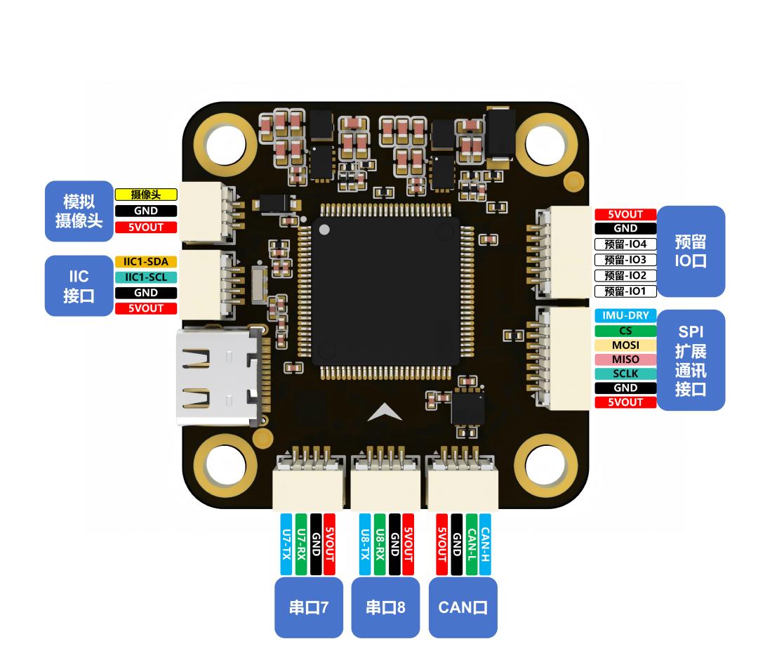
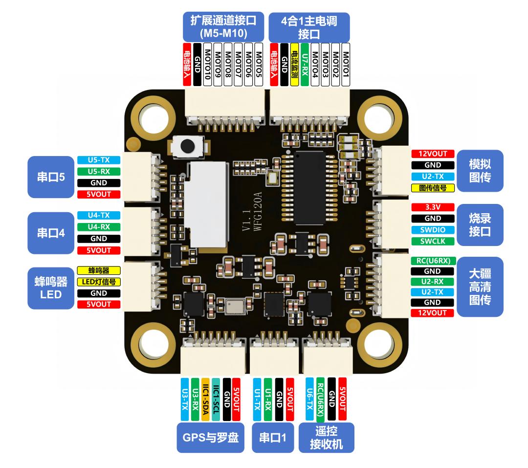
Main technical specifications:
| Item | Specification |
|---|---|
| Main controller | STM32H743VIT6, 480MHz, 2MB Flash |
| Accelerometer & gyroscope | Dual IMU, redundant design |
| Onboard barometer | SPA06 |
| Onboard compass | QMC5883P |
| Onboard OSD chip | AT7456E |
| ESC / servo signal outputs | 10 channels total (MOTO1–MOTO10) |
| 4-in-1 ESC direct connector | 1 (BAT input, GND, MOTO1–MOTO4, current sense, serial RX) |
| ESC / servo expansion connector | 1 (battery positive input, GND, MOTO5–MOTO10) |
| Reserved IO pins | 4 (PIN_IO1 to PIN_IO4) |
| Serial ports | 8 |
| CAN | 1 |
| Dedicated I2C | 1 |
| Analog camera input | 1 |
| Analog video transmitter output | 1 |
| HD video link connector | 1 (supports DJI O3/O4 direct plug-in) |
| STLINK debug port | Supported |
| Buzzer output | Supported |
| LED strip output | Supported |
| Data blackbox | TF card logging supported |
| Onboard BEC outputs | 5V@3A and 12V@3A (automotive-grade power) |
| VBAT input range | 3S–8S |
Have questions about this article? Feel free to contact us at [email protected] — we’re happy to help!
Frequently Asked Questions
What is pymavlink used for?
pymavlink is the official Python library for speaking MAVLink to a flight controller. It converts incoming binary MAVLink messages into Python objects and lets your script send commands back, enabling custom mission logic, telemetry logging and companion-computer autonomy without editing firmware.
Do I need to read the ArduPilot source code for secondary development?
No. The pymavlink approach keeps the flight controller firmware untouched and runs your application on a Raspberry Pi or similar Linux companion computer. ArduPilot’s codebase exceeds 700,000 lines; running a companion computer side-steps that entirely and avoids any risk of contaminating flight-critical code.
Which serial port should I use to connect a Raspberry Pi to an ArduPilot flight controller?
Use an idle port. On the WFG120A, Serial3 is GPS, Serial4 is Mavlink2 telemetry and Serial6 is RC_IN, so this build uses Serial7 (UART7). Any unused port works — check your vendor’s mapping table, then set its function to Mavlink2 and its baud rate to 921600.
Why does my pymavlink script fail after I close the terminal?
Closing the terminal exits the venv virtual environment, so pymavlink is no longer on the Python path. Reopen a terminal and run source ~/venv/bin/activate before starting your script, or automate it with a systemd service that activates the environment for you.
What is the difference between Serial and USART in ArduPilot?
ArduPilot’s Serial1, Serial2 and so on are logical ports that map to the microcontroller’s physical USART/UART peripherals. The mapping differs between boards, which is why each vendor publishes a table. Reading it correctly is the step that prevents the serial misconfiguration most beginners hit.
About Aomway
Aomway supplies FPV and UAV hardware including video transmitters, antennas and link equipment, and follows industrial-grade flight-controller design closely. The team publishes practical guides on ArduPilot integration and companion-computer workflows for UAV developers.