Key Takeaways
- The drone is built around an ESP32-S3 with an on-board Wi-Fi video link and RID broadcast, and can be flown from a phone app, a browser or a physical transmitter.
- Using a ZY-MPU6050 module for attitude sensing avoids hand-soldering a bare IMU, and expansion headers leave room for a barometer, laser rangefinder or position-hold module.
- Two mechanical details decide whether the build succeeds: the PCB must be 1.6 mm thick so the grommets clamp the motors, and the propellers must sit about 2 mm clear of the motor bells.
- Flashing the firmware is done with an online tool and then controlled through the drone’s own Wi-Fi access point — before outdoor flight, the serial number must be burned and RID enabled for registration compliance.
- Most “build failures” are mechanical, not electrical: motors must be perpendicular to the frame, and reversed or misplaced propellers stop the drone from lifting even when all four spin.
A wallet-sized open-source micro drone built around the ESP32-S3 combines a Wi-Fi video link, RID broadcast and three ways to fly it: a phone app, a browser, or a conventional transmitter. The appeal is not raw performance but accessibility — the whole aircraft is simple enough to replicate at a bench, provided a handful of mechanical and regulatory details are handled correctly. This build guide walks through the hardware choices, the two mistakes that most often stop a replica from flying, and the firmware and registration steps that must happen before the first outdoor flight.
Hardware Choices That Keep the Build Simple
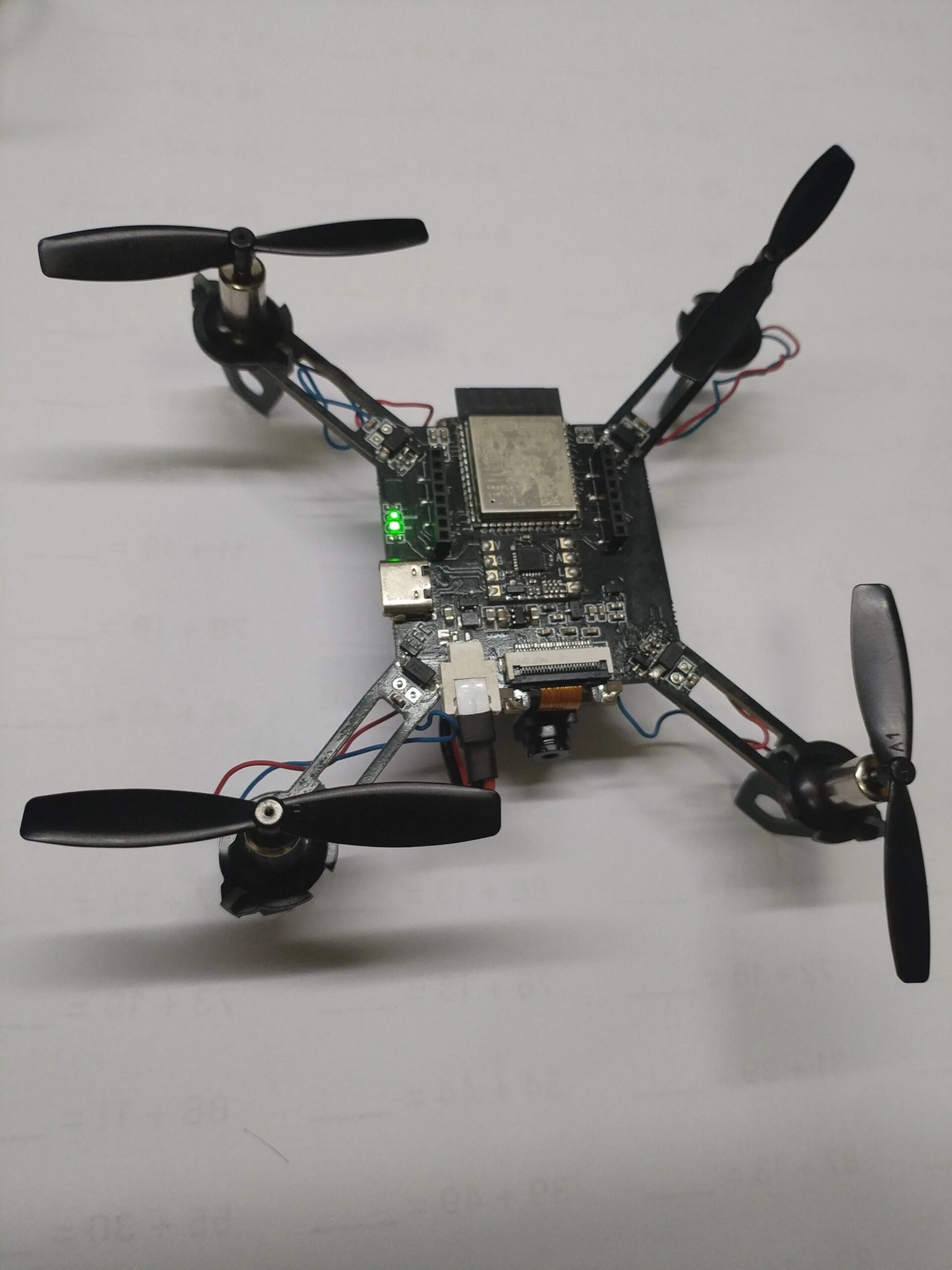
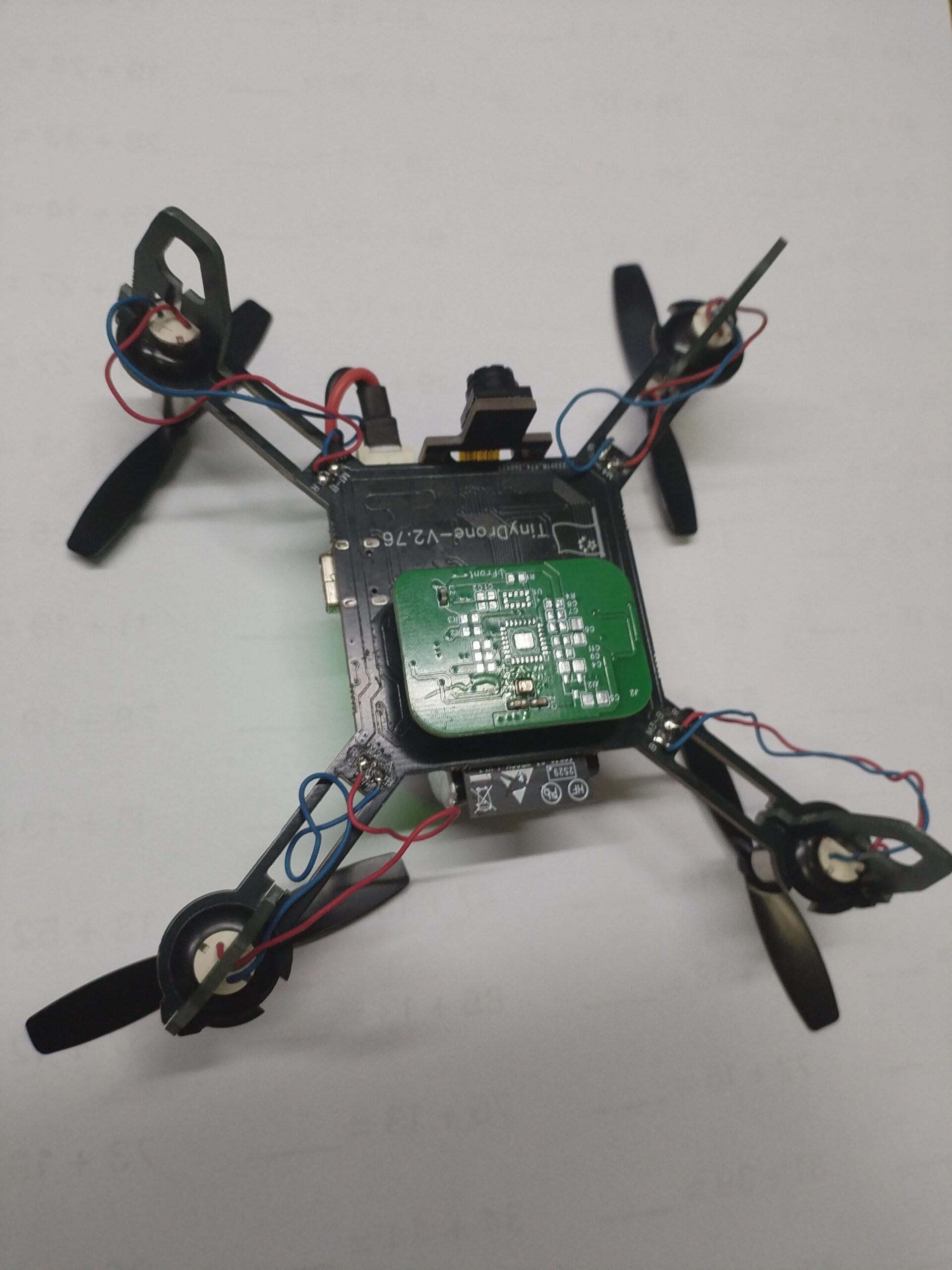
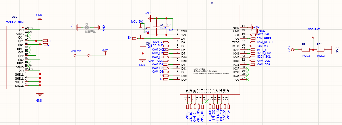
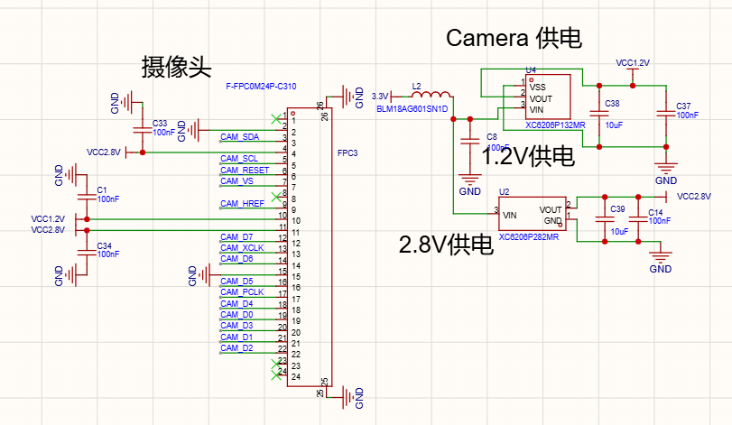
The core is an ESP32-S3, which brings the Wi-Fi video link and the RID broadcast capability on the same chip that runs the flight loop. For attitude sensing, the build uses a ZY-MPU6050 module rather than a bare MPU6050 die — a deliberate shortcut that removes the most error-prone hand-soldering step in a small build and saves debugging time later.
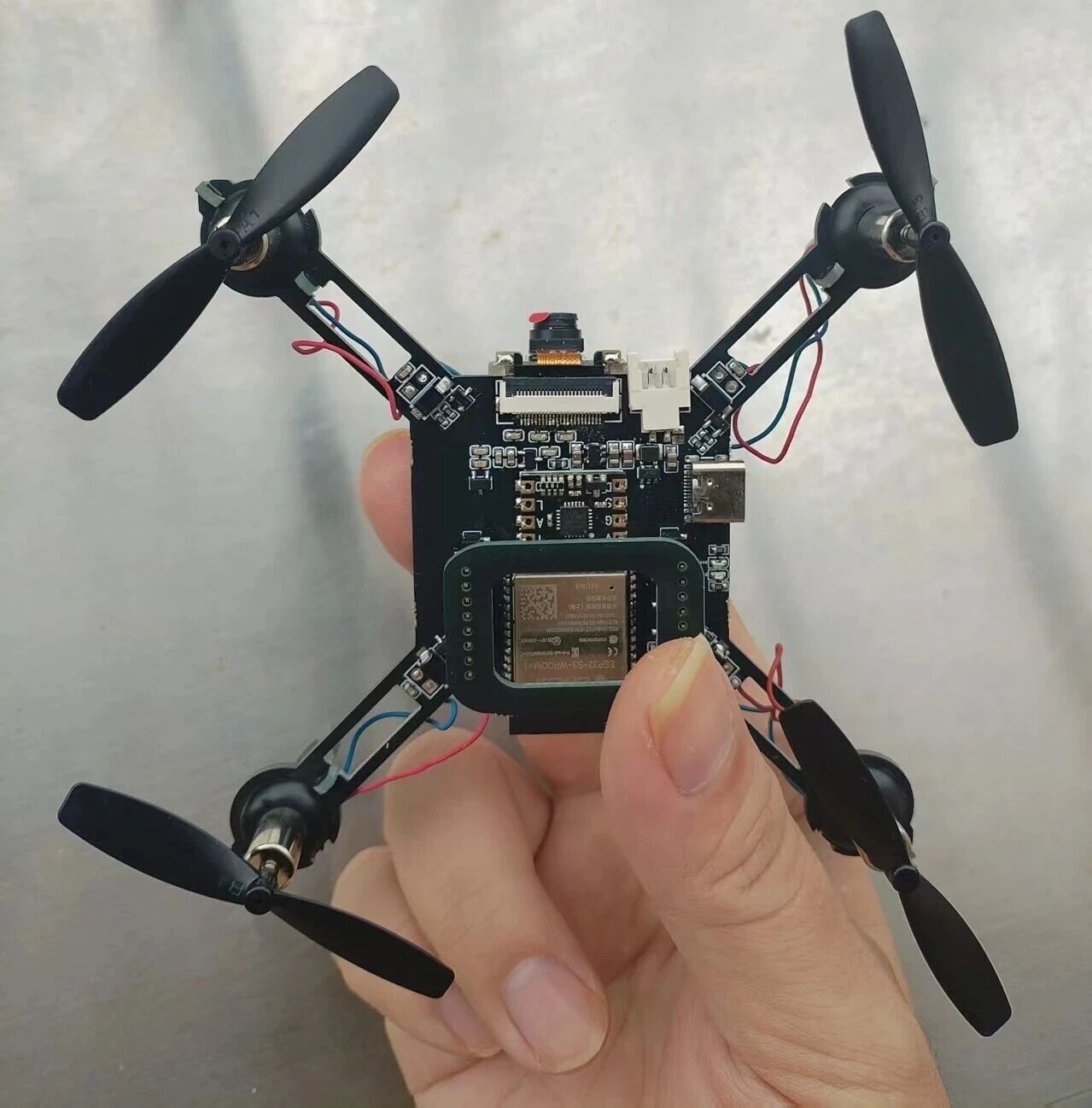
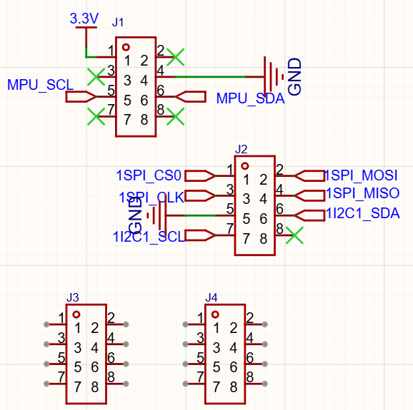
The board also exposes expansion headers, so a barometer, a laser rangefinder or a position-hold module can be added without respinning the PCB. That forward compatibility matters for a micro platform: the airframe is small, but the sensor stack can grow with the mission. For readers planning the wider electronics around a build like this, our open-source flight controller hardware selection guide covers the MCU, IMU and redundancy trade-offs in detail, and the same reasoning applies at micro scale. If you want the ground-station side of a companion computer setup, the pymavlink with a Raspberry Pi companion computer walkthrough is a useful counterpart.
The Two Mistakes That Stop a Replica From Flying
The first is PCB thickness. It must be 1.6 mm. Anything thinner and the rubber grommets cannot clamp against the board properly, leaving a gap that stops the motors from being held securely. On a micro airframe, motor mounting is structural — a loose motor will also destroy the flight tuning, so this is not a cosmetic preference.
The second is propeller clearance. Propellers must not be pressed all the way down against the motor. Leave roughly 2 mm between the propeller and the motor. Pressed flush, the prop binds, draws more current and produces less thrust — the drone may spin up but refuse to lift.
Firmware, Wi-Fi Control and Registration
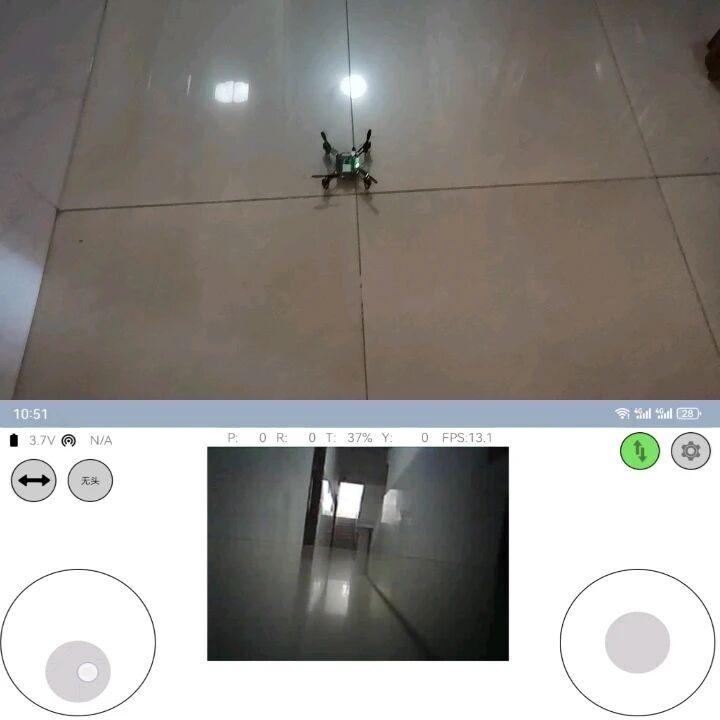
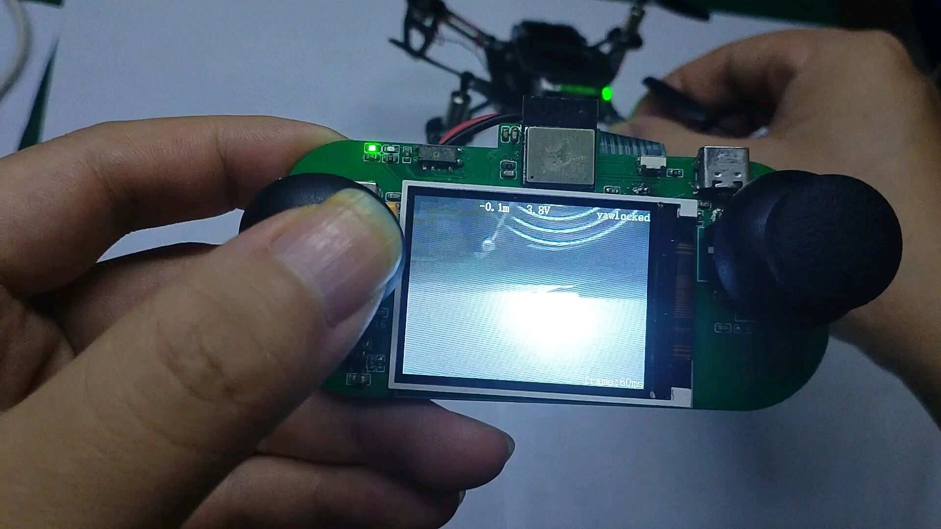
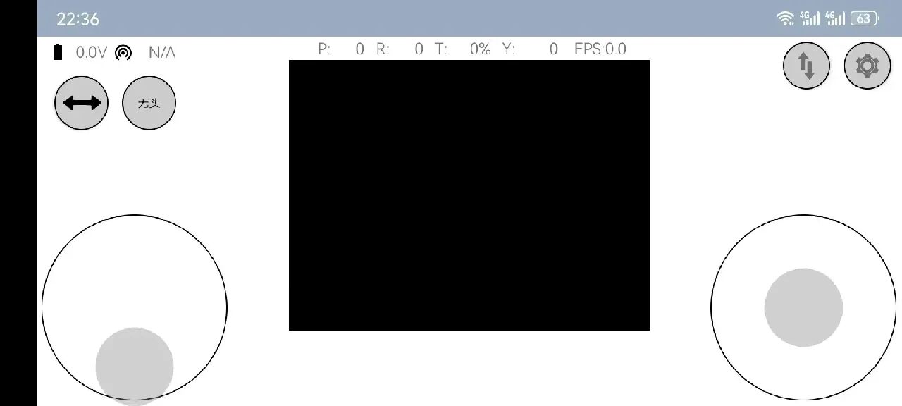
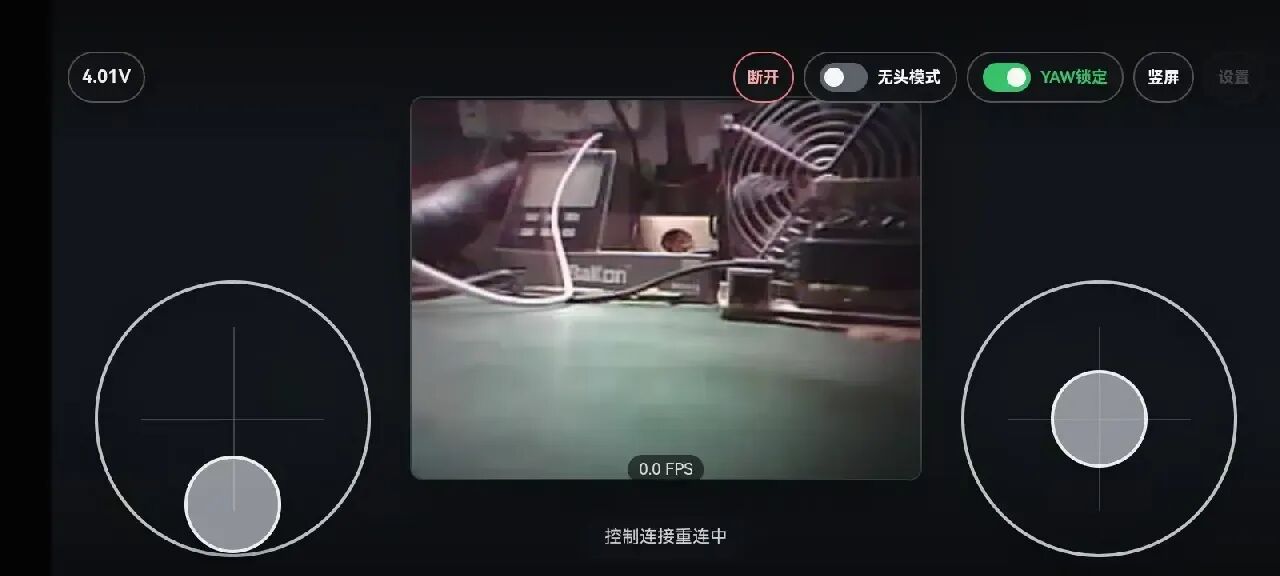
Flashing the firmware is straightforward: use an online tool to burn the image, then connect to the Wi-Fi access point the drone broadcasts. Once connected, an iPhone can control the aircraft directly from the browser — no dedicated app required for the basic workflow, although the phone app offers a cleaner control layout and a live video window.
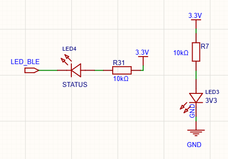
Before flying outdoors, two compliance steps come first: burn the serial number to complete real-name registration, then enable RID. Skipping this is the easiest way to turn a successful test flight into a regulatory problem.
Trimming the Mechanical Structure Before Takeoff
The last step is mechanical. The motors must be as close to perpendicular with the horizontal plane as possible. Even a slight tilt produces a constant heading drift in flight, which cannot be tuned out in software. This is the kind of error that looks like a control-loop problem but is actually a build problem.
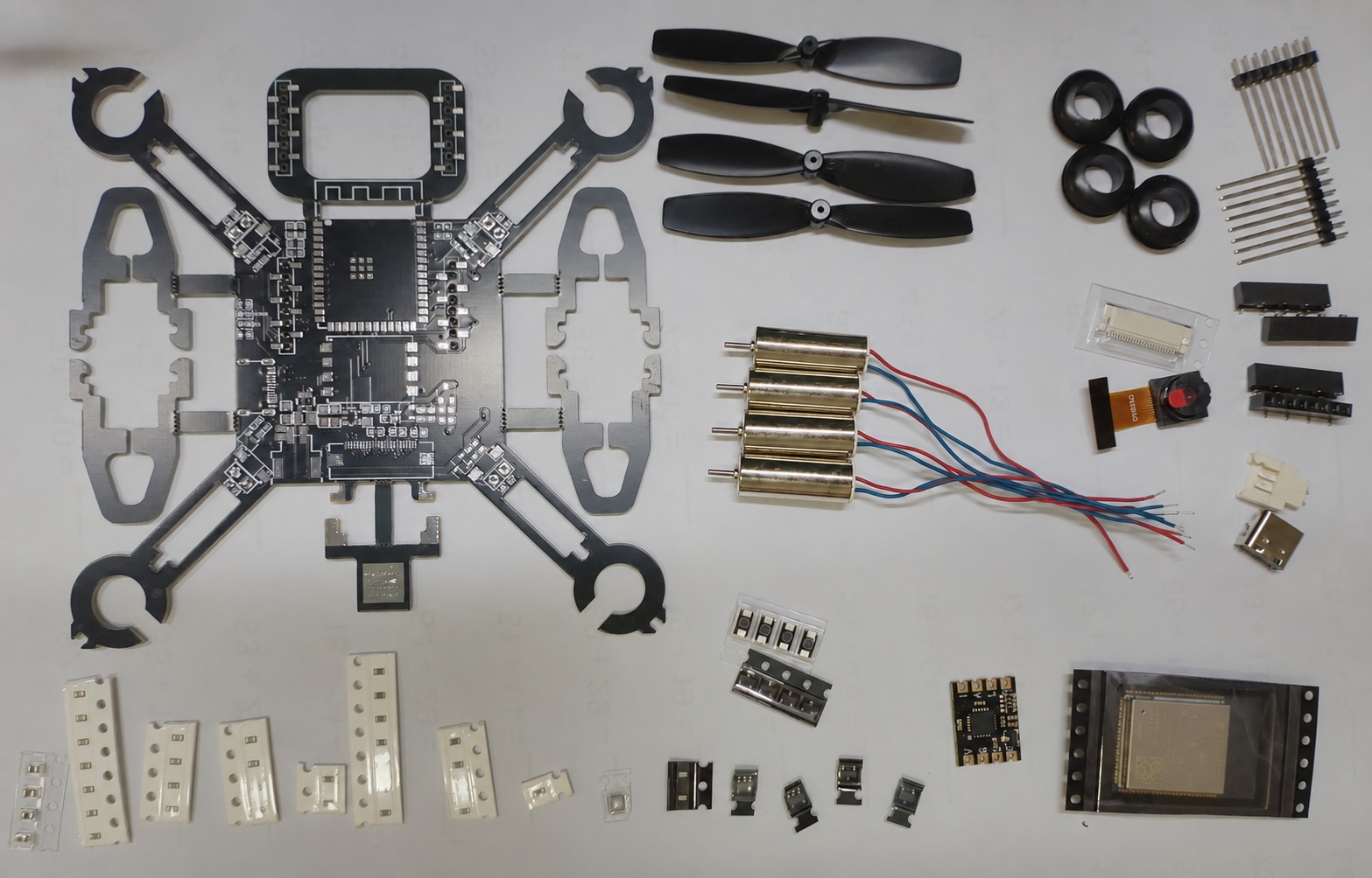
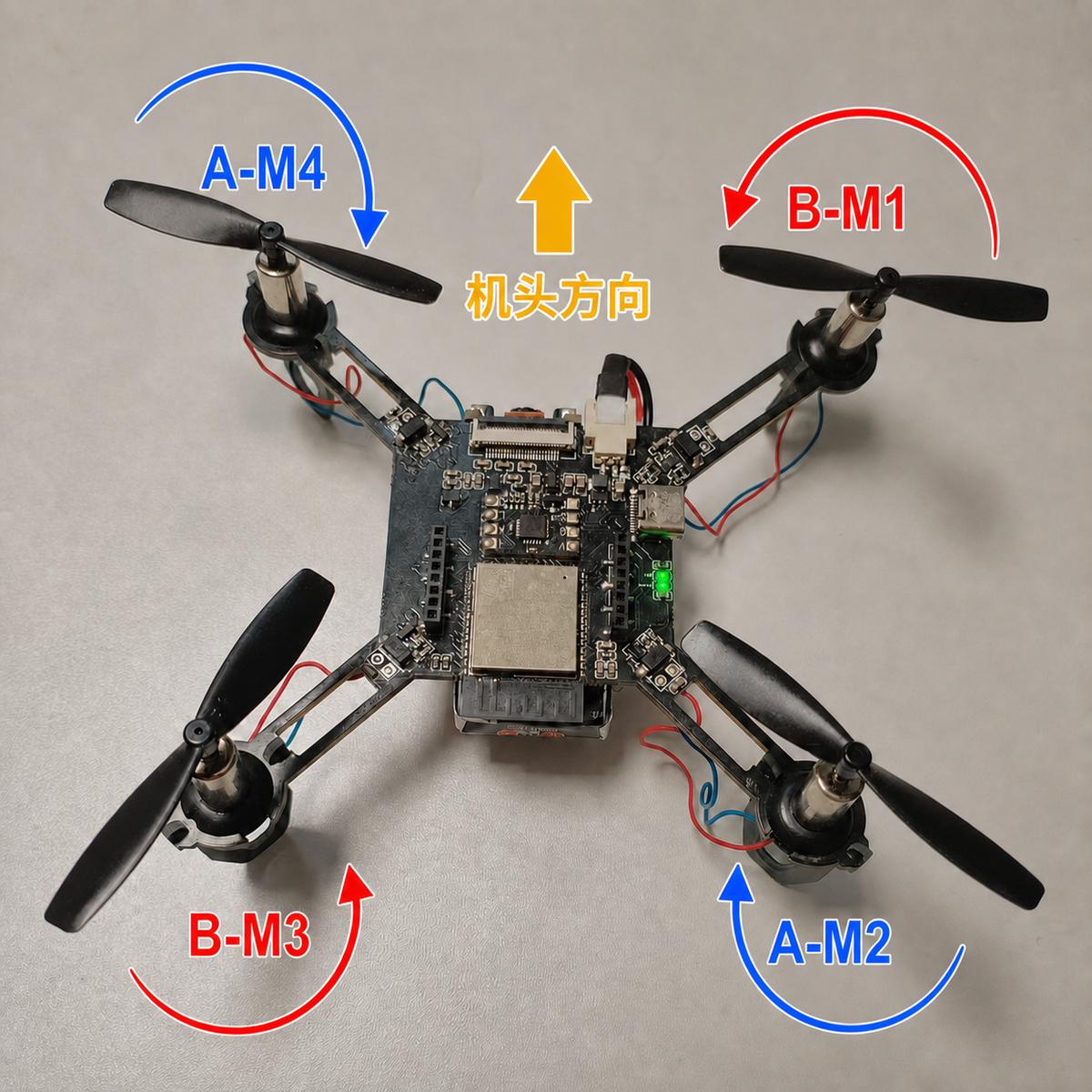
If all four propellers spin but the drone will not get airborne, resist the urge to reach for the multimeter. Check the propeller orientation and position first — a reversed or swapped propeller is a far more common cause than a bad solder joint. The exploded parts view and the motor direction diagram below show how the four motors are labelled and oriented on the frame.
Component Overview
| Subsystem | Choice |
|---|---|
| Flight controller | ESP32-S3 |
| Attitude sensor | ZY-MPU6050 module |
| Video link | On-board Wi-Fi |
| Broadcast | RID (remote ID) |
| Control options | Phone app, browser, transmitter |
| PCB thickness | 1.6 mm |
| Propeller clearance | About 2 mm above motor |
| Expansion | Barometer, rangefinder, position hold |
Have questions about this article? Feel free to contact us at [email protected] — we’re happy to help!
Frequently Asked Questions
What is the ESP32-S3 micro drone used for?
It is a compact open-source FPV platform with Wi-Fi video and RID broadcast, controlled by a phone app, browser or transmitter. It suits indoor experimentation, build practice and small-scale video-link testing.
Why does the PCB have to be exactly 1.6 mm?
The rubber grommets that hold the motors are designed for a 1.6 mm board. Thinner material leaves a gap, so the motors cannot be clamped securely, which hurts both structural rigidity and flight tuning.
How much clearance do the propellers need?
Leave roughly 2 mm between each propeller and the motor. Pressing propellers flush against the motors causes binding, higher current draw and reduced thrust, and the drone may fail to lift off.
Do I need to register the drone before flying?
Yes. Before outdoor flight, burn the serial number to complete real-name registration and then enable RID. These steps are required for compliance and are best done before any outdoor test.
Why does the drone drift or fail to take off?
Most often it is mechanical. A tilted motor produces constant heading drift, and a reversed or misplaced propeller stops lift even though all four motors spin. Check orientation before checking the electronics.
About Aomway
Aomway builds FPV and UAV video transmission hardware, antennas and link equipment for drone platforms of every size, from micro builds to long-range systems. Our team follows open-source airframe projects closely, and we are happy to help with video link and RF questions for compact drones.