

In wireless communication projects, engineers frequently encounter a set of symptoms that appear contradictory at first glance:
- High received signal level, but video keeps freezing
- Device shows connected status, but data cannot be transmitted
- Transmitter is very close, but the network frequently drops
- Switching channels suddenly restores normal communication
- Increasing transmit power shows no significant improvement
- All links become unstable when multiple devices power on simultaneously
What these symptoms tell us:
Whether a wireless link can work properly depends not only on signal strength, but on whether the target signal can be correctly separated from noise and interference.
Many people oversimplify anti-interference as:
- Higher transmit power
- Stronger signal
- Faster frequency hopping
- Auto-selecting a new channel
But real anti-interference is a complete system-level engineering challenge.
It encompasses at minimum:
- Antenna and RF front-end
- Analog filters
- Receiver dynamic range
- Digital filtering
- Spectrum scanning
- Smart frequency selection
- Frequency hopping communication
- MIMO spatial processing
- Dynamic MCS
- FEC forward error correction
- ARQ feedback retransmission
- Mesh route reconstruction
Different technologies address different types of interference problems.
For example:
- Filters mainly suppress out-of-band interference
- Smart frequency selection mainly avoids continuously occupied bands
- Frequency hopping mainly disperses the impact of narrowband interference
- MIMO mainly exploits spatial differences to separate signals
- FEC mainly repairs partially corrupted data
- ARQ mainly retransmits unrecoverable data packets
- Mesh routing mainly bypasses locally interfered nodes
So, this article is not going to answer the simple question:
Is this equipment interference-resistant?
But rather:
Where does interference enter the receiver, which layer of capability does it disrupt, and through what mechanisms does the system restore the link?
1. Noise and Interference Are Not the Same Thing
The signal received by the receiver antenna can be simplified as:
[y(t)=s(t)+i(t)+n(t)]
Where:
- (s(t)): desired target signal
- (i(t)): interference signal from other wireless devices
- (n(t)): random noise from the receiver and environment
What Is Noise?
Noise is typically random, unpredictable electrical signals.
It may come from:
- Environmental thermal noise
- Receiver internal electronic components
- Low-noise amplifier (LNA)
- Mixer
- Analog-to-digital converter (ADC)
- Power supply and digital circuits
Even when no other wireless devices are transmitting nearby, the receiver still has an internal noise floor.
The higher the noise floor, the harder it is for the receiver to detect weak signals. Noise, noise figure, and signal-to-noise ratio directly affect bit error rate, latency, and throughput.
What Is Interference?
Interference is wireless energy from other emission sources that disrupts the reception of the target signal.
Interference may come from:
- Another co-frequency wireless system
- High-power transmitters on adjacent channels
- Wi-Fi or other broadband devices
- Wireless video transmission systems
- Radar and telemetry equipment
- Industrial electronic equipment
- Nearby nodes’ own transmitted signals
- Malicious or non-cooperative emission sources
Noise typically manifests as random background noise, while interference may have distinct frequency, bandwidth, time, and directional characteristics.
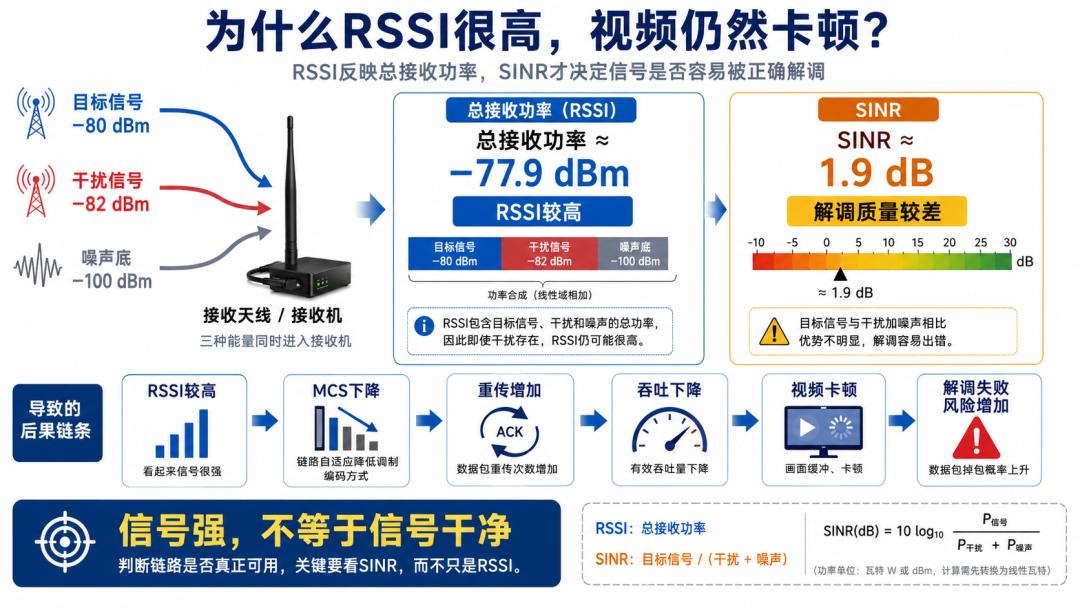
2. Why Does HighRSSIStill Fail to Communicate Normally?
Wireless devices frequently displayRSSIor received power.
Many people see a received level of -70dBmand assume the link quality must be good.
But high received power does not mean all of it is the target signal.
The total energy seen by the receiver may include:
- Target signal
- Co-channel interference
- Adjacent-channel leakage
- Broadband noise
- Receiver internal noise
The key metric that determines whether demodulation is possible is not total received power, but the Signal-to-Interference-plus-Noise RatioSINR:
[SINR=\frac{P_s}{P_i+P_n}]
Where:
- (P_s): Target signal power
- (P_i): Interference signal power
- (P_n): Noise power
Assume the receiver receives:
- Target signal: -80dBm
- Interference signal: -82dBm
- Noise floor: -100dBm
The total received power after combining all three is approximately -77.9dBm.
From the received level perspective, the signal appears strong.
But the calculatedSINRis only about1.9dB.
For high-order MCS, such a SINR may not be able to demodulate properly.
Therefore, the following occurs:
- RSSIappears high
- MCSkeeps decreasing
- Packet error rate increases significantly
- ARQRetransmission count rises
- Video throughput drops
- Link ultimately disconnects
SINR is more valuable than received power alone because it accounts for target signal, interference, and noise simultaneously. Modern wireless testing also combines SINR with channel estimation, MIMO, and demodulation performance for evaluation.
Therefore:
RSSI answers “how much wireless energy the receiver got”, while SINR answers “how much of that energy actually belongs to the target signal”.
3. What Are the Main Types of Wireless Interference?
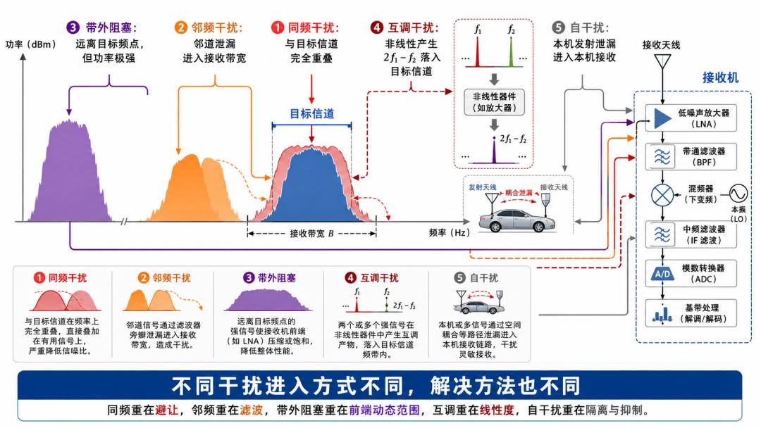
Different types of interference enter the receiver at different points and in different ways.
Therefore, no single method can solve all interference problems.
Common engineering interference can be categorized as follows.
3.1 Co-Channel Interference
Co-channel interference refers to interference signals that occupy the same or highly overlapping frequency range as the target signal.
For example:
- TwoMeshnetworks simultaneously using1.405GHz
- Two devices transmitting on the same channel simultaneously
- Another nearby broadband transceiver occupying the same frequency
Co-channel interference is the hardest to solve through conventional frequency filtering.
Because the target signal and interference signal are in the same frequency range.
If this frequency is directly filtered out, the target signal disappears along with it.
Co-channel interference typically requires the following approaches:
- Time scheduling
- Frequency switching
- Frequency hopping
- MIMO spatial processing
- Power control
- Route switching
- Inter-network spectrum planning
3.2 Adjacent-Channel Interference
Adjacent-channel interference refers to interference signals located near the target channel.
For example, the target device operates at1.400GHzwhile a nearby high-power device operates at1.410GHz.
Although the two devices do not use the exact same center frequency, they can still affect each other due to:
- Transmitted signals do not have ideal rectangular spectra
- Transmitters have out-of-band leakage
- Receiver filters cannot have infinite steepness
- Insufficient receiver adjacent-channel selectivity
- Interference signal power is much higher than the target signal
Adjacent-channel interference mainly tests:
- Transmitter spectral purity
- Receiver filter performance
- Adjacent-channel selectivity
- Receiver dynamic range
- Inter-channel guard band
3.3 Out-of-Band Blocking Interference
Some strong interference signals are far from the target channel and theoretically outside the receiver bandwidth.
But if its power is very strong, it can still degrade receiver performance.
Such signals are typically called blocking signals orBlocker.
For example:
- Target signal is only -100dBm
- A strong signal of -20dBmappears in a nearby band
The difference is80dB.
Even if the strong signal is not in the target channel, it can still compress the receiver’s LNA, mixer, or ADC.
3.4 Intermodulation Interference
When two or more strong signals simultaneously enter nonlinear RF components, new frequency components may be generated.
Assume two strong interference frequencies:
[f_1,\quad f_2]
Receiver nonlinearity may produce:
[2f_1-f_2]
and:
[2f_2-f_1]
If these newly generated frequencies happen to fall within the target channel, communication is disrupted even though the original two interference signals are not on the target frequency.
The receiver’s IP3, linearity, and front-end filtering capability are key factors determining intermodulation performance.
3.5 Self-Interference and Co-Site Interference
In command vehicles, base stations, drones, or communication cabinets, multiple wireless devices are often installed simultaneously.
If antennas are too close, frequency planning is improper, or filtering isolation is insufficient, the following may occur:
- Own transmitter interfering with own receiver
- One transceiver interfering with an adjacent transceiver
- Harmonics falling into other devices’ receive bands
- High-power transmission causing weak-signal receiver blocking
Such problems cannot always be solved by simply changing the frequency.
The following must also be considered:
- Antenna spacing
- Vertical and horizontal isolation
- Antenna polarization
- Duplexers and cavity filters
- Feeder cable layout
- Transmission timing
- Vehicle-wide or site-wide frequency planning
4. Why Does Strong Interference Outside the Operating Channel Still Cause Receiver Drops?
Many people believe:
If the interference is not on my operating channel, the receiver can just filter it out with digital filtering.
This understanding is only partially correct.
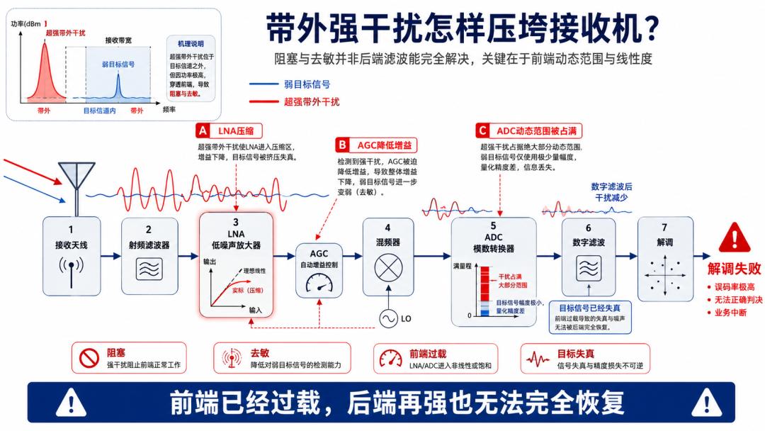
Because before the wireless signal enters the digital processing module, it must first pass through the analog RF front-end.
A typical receiver chain is:
Antenna → Band-pass filter → Low-noise amplifier (LNA) → Mixer → Baseband filter → Analog-to-digital converter (ADC) → Digital filtering → Demodulator
If strong interference has already caused distortion in the analog front-end, subsequent digital algorithms cannot fully recover the original weak signal.
4.1 LNA Compression
The LNA is responsible for amplifying weak signals received by the antenna.
But the amplifier can only maintain linearity within a certain input power range.
When strong interference enters, the amplifier may enter the compression region.
At this point:
- Amplification gain decreases
- Target signal distortion
- New spurious and intermodulation components generated
- Receiver sensitivity degrades
4.2 AGC Reduces Receive Gain
Receivers typically have AGC (automatic gain control).
AGC adjusts receiver gain based on total received energy.
If a very strong out-of-band or adjacent-channel signal enters the receiver, AGC may mistakenly assume the input signal is too strong and reduce front-end gain.
The result is:
- Strong interference is not fully eliminated
- Weak target signal further suppressed
- The receiver exhibits“reduced sensitivity”
This phenomenon is also called receiver desensitization orDesensitization.
4.3 Mixer Intermodulation Products
When strong signals enter the nonlinear mixer, new frequency components may be generated.
Once these intermodulation products fall within the target channel, back-end filters have difficulty separating them from the target signal.
4.4 ADC Dynamic Range Limitations
The ADC needs to accommodate both the weak target signal and strong interference simultaneously.
If strong interference occupies most of the ADC’s quantization range, the weak target signal is left with very few effective quantization bits.
If interference continues to increase, the ADC may also exhibit clipping and distortion.
The core value of a high-dynamic-range receiver is maintaining the ability to receive weak target signals even in the presence of strong blocking signals. Analog Devices’ broadband receiver literature emphasizes that analog and digital filtering must jointly handle out-of-band blocking signals, while the front-end and ADC must have sufficient dynamic range.
Therefore:
Digital filtering can only process signals that have been linearly captured by the receiver; if the analog front-end has already overloaded, back-end algorithms cannot magically recover lost information.
5. Layer 1 Anti-Interference: Protect the Receiver RF Front-End First
Before performing smart frequency selection, frequency hopping, and digital processing, the receiver must first be protected from being overwhelmed by strong signals.
This layer relies primarily on hardware design.
5.1 RF Band-Pass Filtering
Band-pass filters only allow signals near the target operating band to enter the receiver and attenuate distant out-of-band signals.
Filters are mainly used for:
- Suppressing high-power out-of-band signals
- Reducing harmonic and spurious effects
- PreventingADCoverload
- Reducing intermodulation risk
- Improving receiver blocking performance
But filters cannot resolve fully overlapping co-channel interference.
Because co-channel interference is within the same passband as the target signal.
5.2 High-Linearity RF Components
The LNA, mixer, and other front-end components need sufficient:
- 1dB1dB compression point
- IIP2
- IIP3
- Maximum input power
- Dynamic range
Better linearity means lower probability of compression and intermodulation caused by strong interference.
5.3 Intelligent AGC Control
AGC should not quickly reduce gain simply by seeing total power.
It also needs to balance the following objectives:
- Preventing front-end and ADC overload
- Preserving weak target signal
- Adapting to burst signals
- Avoiding frequent gain oscillation
- Maintaining demodulator stability
5.4 Antenna and Site Isolation
For multiple devices on the same vehicle, drone, or site, self-interference can be reduced through:
- Increasing antenna spacing
- Using different antenna heights
- Using orthogonal polarization
- Adding shielding and isolation
- Properly routing feeder cables
- Adding duplexers or cavity filters
- Preventing transmit frequencies from falling into other receivers’ passbands
- Coordinating transmission timing
The core of this anti-interference layer is:
Before the signal enters the ADC, prevent strong interference from disrupting the receiver’s linear operating state.
6. Layer 2 Anti-Interference: What Does Spectrum Scanning Actually Scan?
Only after the RF front-end is not overloaded can the system further assess the current spectrum environment.
Spectrum scanning is not simply checking whether a frequency“has a signal”.
It needs to observe at least:
- Received energy at each frequency
- Noise floor
- Channel occupancy time
- Interference duration
- Interference bandwidth
- Whether interference appears periodically
- Packet error rate
- Current linkSINR
- CurrentMCSand throughput
Why a Single Spectrum Snapshot Is Not Enough
Some interference is not persistent.
For example:
- Burst interference appearing every few seconds
- Periodically operating radar signals
- Time-slot transmissions from other systems
- Sweep signals
- Frequency-hopping signals
- Occasionally activated high-power equipment
If only a single instantaneous spectrum snapshot is viewed, interference may not be visible.
Therefore, practical spectrum monitoring typically requires a time dimension.
Common display methods include:
- Real-time spectrum
- Spectrogram / waterfall display
- Frequency occupancy statistics
- Peak hold
- Long-term noise floor recording
Does Low Spectrum Energy Mean a Good Channel?
Not necessarily.
A low instantaneous energy level at a certain frequency may simply mean the interference source is not currently transmitting.
It also needs to be combined with:
- Long-term occupancy rate
- Packet error rate
- LinkSINR
- Adjacent-channel high-power signals
- Service performance after channel switching
Therefore, true smart frequency selection cannot rely solely on the instantaneous RSSI.
7. How Does Smart Frequency Selection Work?
The goal of smart frequency selection is:
Within the allowable frequency range, find working channels that are more favorable for network-wide communication. Smart frequency selection is not simply “auto-frequency-switching”; rather, each node dynamically selects the most suitable receive frequency based on its own wireless environment.
See: “Smart Frequency Selection Anti-Interference: From Passive Interference Avoidance to Active Optimal Link Selection”
Recommended reading: Smart Frequency Selection Anti-Interference: From Passive Interference Avoidance to Active Optimal Link Selection
8. Why Can Frequency Hopping Improve Anti-Interference Capability?
Smart frequency selection typically chooses a relatively clean channel from multiple candidates to continue operation.
Frequency hopping is different.
Frequency hopping systems rapidly switch between multiple frequencies according to pre-agreed rules.
Assume the frequency hopping channel set is:
[f_1,f_2,f_3,f_4,\ldots,f_N]
The system may operate according to a certain sequence:
[f_3\rightarrow f_7\rightarrow f_1\rightarrow f_9\rightarrow f_4]
Both communicating parties must arrive at the same logical channel at the corresponding time, otherwise communication cannot be completed.
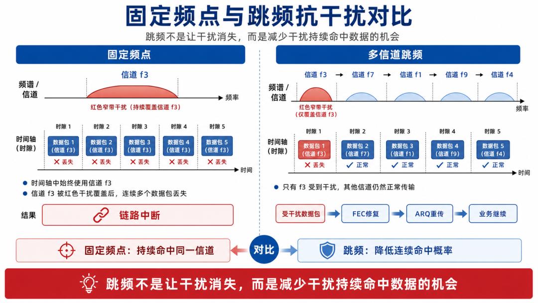
8.1 Fixed-Frequency Systems Under Narrowband Interference
Assume a fixed-frequency system always operates on channel3.
If channel 3 experiences persistent interference, all data packets will be affected.
8.2 Frequency-Hopping Systems Under Narrowband Interference
Assume the system hops among 16 channels, and interference only covers one of them.
Then only when hopping to the interfered channel will some data packets be affected.
Other frequency hopping time slots can still transmit normally.
Combined with:
- FEC forward error correction
- Data interleaving
- ARQ feedback retransmission
the system can recover partially interfered data.
8.3 Factors Affecting Frequency Hopping Performance
Frequency hopping anti-interference capability is affected by:
- Number of hopping channels
- Available frequency span
- Individual channel bandwidth
- Dwell time
- Hop rate
- Hopping sequence
- Time synchronization accuracy
- Proportion of interfered channels
- FECand retransmission capability
If interference only covers a narrow frequency range, a larger hopping set is generally more beneficial.
If interference covers the entire hopping band, hopping alone cannot fully avoid it.
Why Is High-Speed Frequency Hopping a Key Capability for Wireless Ad Hoc Network Anti-Interference?
Smart Frequency Selection vs. Frequency Hopping
Smart frequency selection
is more like:
Finding a relatively clean road and continuing to drive on it.
Suitable for handling:
- Persistent fixed-frequency interference
- Randomly appearing partial-band interference
- Environments where candidate frequencies have significantly different quality
Frequency hopping
is more like:
Constantly changing roads so interference cannot block all transmission opportunities.
Suitable for handling:
- Narrowband persistent interference
- Interference with constantly changing frequency positions
- Countering unpredictable frequency occupancy
The two can be used together:
- First exclude severely interfered channels through spectrum scanning
- Then perform frequency hopping within the remaining available channel set
Adaptive frequency hopping mode can configure a set of working channels within the operating band, with up to 256 channels and over 1000 hops per second, combined with dynamic MCS, FEC, and ARQ to improve transmission effectiveness. Actual hopping range, channel count, and hop rate are subject to product model, channel bandwidth, licensed frequency band, firmware, and regulatory conditions; refer to actual equipment test results.
It must also be noted that:
Frequency hopping is an anti-interference and spectrum dispersion mechanism, not equivalent to data encryption.
Even with frequency hopping, critical services still require independent authentication and data encryption mechanisms.
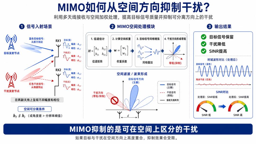
9. MIMO: Why Can It Suppress Interference from the Spatial Dimension?
Frequency filtering separates signals by frequency differences.
Time scheduling avoids collisions by time differences.
MIMO spatial processing exploits:
The spatial characteristic differences produced when target and interference signals arrive at multiple antennas from different directions and paths.
Taking a dual-antenna receiver as an example, the received signal can be simplified as:
[\mathbf{y}
\mathbf{h}_s s+\mathbf{h}_i i+\mathbf{n}]
Where:
- (\mathbf{h}_s): spatial channel of the target signal at the two antennas
- (\mathbf{h}_i): spatial channel of the interference signal at the two antennas
- (s): target data
- (i): interference signal
- (\mathbf{n}): noise
The receiver can assign complex weights to different antenna signals:
[z=\mathbf{w}^{H}\mathbf{y}]
The weights contain amplitude and phase information.
The system’s goals are:
- Maximize coherent combining of the target signal
- Maximize cancellation of the interference signal
- Improve the final outputSINR
This processing can be understood as receive spatial filtering.
Beamforming and spatial filtering control the amplitude and phase of each antenna channel to form high gain in the target direction and reduce response or form nulls in the interference direction.
9.1 Requirements for MIMO Spatial Interference Suppression
MIMO does not unconditionally eliminate interference.
It requires some spatial separability between the target and interference signals.
For example:
- Target signal comes from the front
- Interference signal comes from the side-rear
- They arrive via different reflection paths
- They have different polarization characteristics
When multiple antennas observe different spatial channels, the receiver has an opportunity to separate them.
9.2 Scenarios Where MIMO Performance Is Limited
Target and Interference Come from Nearly the Same Direction
If both have highly similar spatial characteristics, the receiver cannot easily suppress interference without also degrading the target signal.
Too Many Interference Sources
The number of antennas determines the spatial degrees of freedom available to the system.
A 2×2 MIMO system cannot simultaneously completely eliminate an arbitrary number of independent interference sources from any direction.
Interference Has Already Overloaded the Front-End
If the LNA or ADC has already been compressed by strong interference, digital spatial processing cannot fully recover the distorted signal.
Antenna Correlation Too High
If two antennas are too close, have the same polarization, and are in similar environments, the two receive channels may be highly correlated, reducing spatial processing gains.
Therefore:
MIMO spatial anti-interference is a supplement to RF filtering, frequency selection, and hopping — not a replacement.
10. Dynamic MCS, FEC, and ARQ: What Problems Does Each Solve?
When interference cannot be fully avoided, the system can also adjust transmission methods to improve data recovery probability.
But the roles of these three mechanisms should not be confused.
10.1 Dynamic MCS — Lowering the Demodulation Threshold
Higher-order modulation can transmit more bits but requires higherSINR.
For example:
- 64QAMand256QAMHigh throughput but high anti-interference requirements
- 16QAMModerate
- QPSKandBPSKLower throughput but stronger robustness
When the link is interfered, the system can lower MCS:
- Reduce bits per symbol
- Increase coding redundancy
- Lower requiredSINR
- Prioritize maintaining connection
Dynamic MCS’s trade-off is:
The link may stay connected, but available throughput decreases.
10.2 FEC — Correcting Errors at the Receiver
FEC is Forward Error Correction.
The sender adds redundant check information to the original data.
Even if the receiver receives some erroneous bits, it can recover the original data using redundancy relationships.
FEC’s advantages are:
- No need to wait for retransmission requests
- Can reduce packet loss under mild interference
- Suitable for latency-sensitive services
- Can handle a certain range of random errors
But FEC capability is limited.
If the number of errors exceeds the correction capability of the code, the data packet still cannot be recovered.
10.3 ARQ — Retransmitting When Recovery Fails
ARQ is Automatic Repeat reQuest.
After detecting a packet error or missing data, the receiver requests the sender to retransmit.
ARQ can improve data integrity but at the following costs:
- Consuming additional channel resources
- Increasing end-to-end latency
- Increasing latency jitter
- Reducing effective throughput
If interference persists, retransmitted packets will continue to fail.
Therefore:
- FECis responsible for repairing limited errors
- ARQis responsible for retransmitting unrepaired data
- MCSis responsible for lowering the demodulation threshold for subsequent data
None of them can directly remove interference from the spectrum.
Huaxiasheng public materials list independent-link dynamic MCS, FEC, and ARQ as the adaptive transmission mechanisms of MIMOmesh, for reducing packet loss and improving effective transmission capability.
11. How Does a Mesh Network Bypass Interference at the Network Layer?
Interference does not necessarily cover the entire area.
Many field interference sources are distinctly localized.
For example:
- Strong interference near industrial facilities
- High-power emitter on a building rooftop
- Co-site interference near a vehicle
- Poor spectrum environment in a valley
- A relay node experiencing receiver blocking
Assume the original route is:
A → B → C → D
where node C is experiencing severe interference nearby.
The network can find an alternate path:
A → B → E → F → D
At this point, the network has not eliminated the interference near C.
It simply routes traffic around the interfered area.
The network layer can perform:
- Link quality detection
- Neighbor updates
- Routing cost adjustment
- Interfered link cost increase
- Backup path calculation
- Traffic re-routing
- Multi-path load distribution
11.1 When Route Switching Works
Suitable when:
- Interference only affects local nodes
- Other available paths exist in the network
- Backup paths have sufficient throughput
- Route switching time meets service requirements
11.2 When Route Switching Does Not Help
In the following cases, simply switching routes cannot solve the problem:
- All nodes are in the same strong interference zone
- Interference covers the entire usable band
- Network has only one physical path
- Backup paths are also interfered
- Interference power has blocked all receivers
In these cases, combine:
- Frequency switching
- Frequency hopping
- Antenna adjustment
- Increasing frequency isolation
- Deploying elevated relays
- Changing operating band
- Combining other communication methods
Therefore:
The Mesh network layer addresses “which path is more usable” and cannot replace the physical layer in solving “whether each hop can correctly demodulate”.
12. Why Doesn’t Increasing Transmit Power Necessarily Solve Interference?
Increasing transmit power is not entirely useless.
In noise-limited, weakly interfered environments, increasing target signal power can improve SNR.
But in complex interference environments, it is not necessarily the most effective approach.
12.1 Case 1: Co-Channel Interference Power Is Constant
If the target signal increases 3dB while external interference remains unchanged, SINR may theoretically improve somewhat.
But the increased power also propagates farther, potentially interfering with other nodes and networks.
12.2 Case 2: Both Sides Increase Power
If two co-frequency networks continuously increase transmit power:
- Target signal increases
- Interference signal also increases
- SINRMay not improve
- Overall spectrum environment worsens
This is like two people in the same room simultaneously raising their voices.
The result may not be clearer hearing, but a noisier room.
12.3 Case 3: Nearby Strong Transmitter Causes Blocking
If the problem is receiver compression from a nearby strong signal, increasing the other end’s transmit power may not solve the receiver’s insufficient dynamic range.
More effective methods may include:
- Adding filters
- Increasing antenna spacing
- Adjusting operating frequency
- Reducing co-site transmit power
- Improving site isolation
12.4 Case 4: Interference Covers the Entire Channel
Increasing power may temporarily make the target signal exceed the interference.
But if interference continues to strengthen, it will still fail.
It also brings:
- Increased power consumption
- Increased heat generation
- Reduced battery life
- Increased out-of-band emissions
- Regulatory limits
- Interference to other systems
Therefore, the reasonable anti-interference sequence is usually not:
Maximize transmit power first.
But rather:
First determine the interference type, then select targeted methods such as filtering, isolation, frequency selection, frequency hopping, spatial processing, coding, or routing.
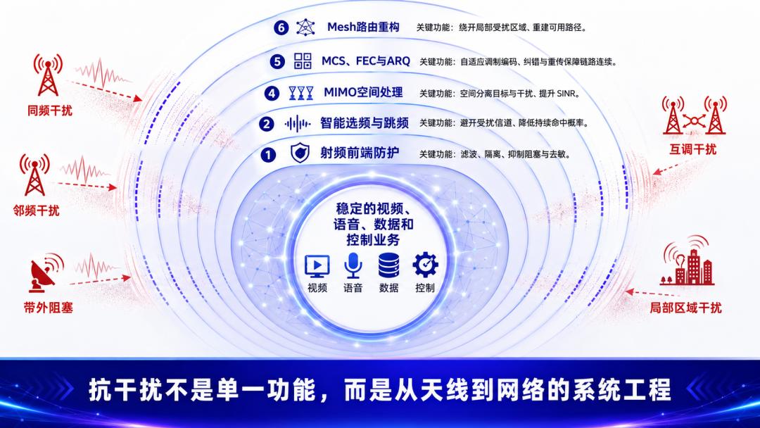
13. How Many Layers Should a Complete Anti-Interference System Have?
A truly reliable wireless network should not depend on any single function.
It needs at least six layers of anti-interference capability.
Layer 1: RF Front-End Protection
Including:
- Antenna isolation
- Band-pass filtering
- High linearityLNA
- High-dynamic-range ADC
- ProperAGC
- Co-site frequency planning
Goal:
Prevent strong signals from directly overwhelming the receiver.
Layer 2: Spectrum Awareness
Including:
- Real-time spectrum scanning
- Noise floor detection
- Channel occupancy statistics
- Burst interference identification
- Long-term spectrum recording
Goal:
Know where the interference is, when it appears, and how wide it spans.
Layer 3: Frequency Avoidance
Including:
- Smart frequency selection
- Channel switching
- Interfered channel blacklist
- Multi-channel frequency hopping
- Dynamic channel set
Goal:
Avoid staying on the same frequency resource as the interference for extended periods.
Layer 4: Spatial Processing
Including:
- MIMOReceive diversity
- Spatial filtering
- Beamforming
- Interference direction nulling
- Multi-antenna weighted combining
Goal:
Exploit spatial differences between target and interference signals to improve output SINR.
Layer 5: Data Recovery
Including:
- Dynamic MCS
- Data interleaving
- FEC forward error correction
- CRCCRC check
- ARQ feedback retransmission
- Service priority
Goal:
When partial data is interfered, recover as much effective service as possible.
Layer 6: Network Reconfiguration
Including:
- Link quality detection
- Dynamic routing
- Interfered node bypass
- Backup relay
- Multi-band network
- Ground-drone coordination
Goal:
When a link is truly unavailable, find another path.
The anti-interference system described in Huaxiasheng public materials for MIMOmesh covers time-domain and frequency-domain digital filtering, MIMO smart antennas, spectrum scanning, smart frequency selection, adaptive frequency hopping, dynamic MCS, FEC, and ARQ across multiple dimensions. Actual effectiveness cannot be judged by individual parameters alone; it must be validated under real interference types and service conditions.
Conclusion
When the network drops upon interference, it is often not a single function failing.
It may occur at different points:
- Co-channel signal directly reducingSINR
- Adjacent-channel strong signal entering receiver passband
- Out-of-band blocking compressing the LNA
- AGC pulled down by strong signal
- Mixer generating in-band intermodulation
- ADC dynamic range consumed by strong interference
- Packet errors exceedingFECcapability
- ARQRetransmissions consuming the channel
- A relay node surrounded by localized interference
Therefore, a reliable wireless network cannot rely solely on increasing transmit power.
It requires bottom-up layered processing:
- RF filtering blocks out-of-band strong signals
- High-dynamic-range receiver prevents blocking
- Spectrum scanning detects interference
- Smart frequency selection finds better channels
- Frequency hopping disperses narrowband interference
- MIMOimproves SINR from the spatial dimensionSINR
- Dynamic MCSlowers the demodulation threshold
- FECrepairs partial errors
- ARQretransmits unrepaired data
- Mesh bypasses locally unavailable links
Therefore, real anti-interference is not simply:
We support frequency hopping.
But rather:
When interference enters the system from frequency, time, spatial, and power dimensions, does the network possess multi-layer mechanisms to detect it, avoid it, suppress it, repair it, and when necessary, reselect transmission paths.
In one sentence:
Filtering protects the receiver, frequency selection and hopping avoid interference, MIMO separates signals spatially, FEC and ARQ recover data, Mesh finds new available paths.
Key Takeaways
- Anti-interference is a multi-layer system challenge — from RF front-end filtering to network-level route switching.
- High RSSI does not guarantee good communication — the key metric is SINR (Signal-to-Interference-plus-Noise Ratio).
- Frequency hopping protects against narrowband interference but not broadband jamming covering the entire band.
- MIMO spatial processing requires adequate antenna separation and works best when interference arrives from different directions.
- Increasing transmit power is not always the answer — it can worsen co-site interference and AGC compression.
- Aomway mesh radio systems integrate multi-layer anti-interference protection across all 6 layers for reliable communication in contested RF environments.
Frequently Asked Questions (FAQ)
Q1: Why does my mesh network show strong RSSI but still have poor throughput?
RSSI measures total received power including interference. A strong interferer can produce high RSSI while actual SINR remains poor. What matters is whether your receiver can separate the desired signal from interference. Aomway systems include spectrum analysis tools that help distinguish signal quality from raw power readings.
Q2: Does frequency hopping protect against all types of interference?
No. Frequency hopping is effective against narrowband interference by spreading energy across multiple frequencies. However, it does not help against broadband jamming covering the entire operating band, or against out-of-band blocking that saturates the receiver front-end before hopping occurs.
Q3: Will increasing transmit power help when my network experiences interference?
It depends. If both sides of a co-channel link increase power equally, SINR may not improve. In co-site scenarios, higher transmit power can cause self-interference or AGC desensitization. Power increase helps only when interference power is fixed and the receiver is not already saturated.
Q4: Can MIMO completely eliminate interference?
MIMO can significantly suppress interference by exploiting spatial diversity, but it requires sufficient antenna separation and works best when interference arrives from different directions than the desired signal. When interference and desired signal arrive from the same direction, MIMO spatial filtering capability is limited.
Q5: How many layers should a practical anti-interference mesh system have?
A robust system needs all 6 layers working together: RF front-end protection, spectrum awareness, frequency avoidance, spatial processing, data recovery, and network reconfiguration. Missing any layer creates a vulnerability. Aomway mesh products implement protection at every layer for maximum resilience.
If you have questions about anti-interference mesh network design or Aomway multi-layer protection solutions, contact us at [email protected].
Next IssuePreview
Preview: Why Does a Mesh Network Stay Connected When Vehicles Are Moving?
The next issue will start from dynamic topology and routing fundamentals, diving deep into:
- How nodes discover nearby devices
- How neighbor tables are built and updated
- How link quality is calculated
- Why routes change
- How paths switch when nodes move
- Differences between route switching and traditional roaming
- How the network self-heals when a relay node leaves
- How to avoid network oscillation when convoys, drones, and individuals move simultaneously
- Why video may briefly stutter during route switching
- How a real mobile ad hoc network should be tested
