

A single fixed-wing UAV can handle inspection, mapping, search, and communication relay. When multiple aircraft coordinate, mission coverage, duration, and system redundancy can all improve significantly. But having multiple aircraft in the air simultaneously does not equal formation flight. Fixed-wing formation also requires each aircraft to maintain a stable relative relationship, exchange necessary information, and execute safety strategies in the event of communication anomalies, member dropout, or trajectory conflicts.
Key Takeaways
- Fixed-wing formation requires analyzing system layering, communication topology, coordination algorithms, and flight vehicle constraints together — not just algorithm frameworks
- Centralized, distributed, and hybrid architectures determine where information flows and where decisions are computed; each has distinct fixed-wing implementation requirements
- All formation methods (leader–follower, virtual structure, consensus, vector field, MPC) must pass a flyability check: curvature limits, airspeed envelope, roll angle constraints, and communication latency
- Aomway offers customizable FPV and telemetry solutions that complement fixed-wing formation systems, enabling real-time video feedback and data link monitoring
- When coordination conditions degrade, the priority shifts to single-aircraft flight safety — formation dissolve, altitude stagger, loiter, or individual return-to-home
1. System Architecture: Where Formation Algorithms Live
A fixed-wing formation system comprises mission planning, formation coordination, single-aircraft guidance, flight control and state estimation, and safety supervision. These layers cannot be handled by a single controller alone. Once the algorithmic layer is clear, centralized, distributed, and various formation methods can be compared within the same system framework.
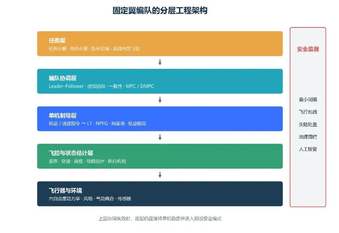
- Mission Layer: Handles task decomposition, member roles, target areas, no-fly zones, and formation transitions. This layer typically runs at low frequency and can be managed centrally by a ground station or lead aircraft.
- Formation Coordination Layer: Generates desired slot positions, trajectories, speeds, and time progress for each aircraft using leader–follower, virtual structure, consensus, or MPC methods.
- Single-Aircraft Guidance Layer: Converts desired trajectories into flyable commands — flight path angle, roll angle, climb rate, airspeed, or acceleration commands. L1, NPFG, vector field, and trajectory tracking controllers reside here.
- Flight Control & State Estimation Layer: Completes attitude control, airspeed and altitude control, navigation estimation, and actuator control. This layer should maintain stable flight even if the upper formation program exits.
- Safety Supervision Layer: Monitors flight envelope, geofences, minimum inter-vehicle distance, communication timeouts, and member status. Triggers formation dissolve, altitude stagger loiter, or single-aircraft return-to-home based on anomaly severity.
This layered approach avoids upper-level algorithms directly manipulating control surfaces and preserves the flight controller’s safety capability when coordination programs encounter anomalies.
2. Fixed-Wing Constraints Must Enter Formation Algorithms
Using a simplified 3D coordinated turn model for aircraft i, with roll angle limited to |φ| ≤ φ_max, the minimum coordinated turn radius is approximately:
R_min ≈ V² / (g · tan φ_max)
These relationships impose several direct constraints on formation algorithms:
- Continuous Forward Flight: Fixed-wing aircraft have minimum airspeed and cannot hover or translate laterally to eliminate formation error.
- Turn Curvature Constraint: The motion trajectory of desired slot positions must satisfy minimum turn radius. When the lead aircraft maneuvers sharply, wingmen may not maintain rigid offsets.
- Speed & Energy Constraints: Inner and outer formation members require different speeds and roll angles in turns. Speed coordination must not exceed throttle, lift, and climb capabilities.
- Wind & Estimation Error: Each aircraft experiences different wind fields. GNSS errors and timestamp biases enter the relative position loop directly.
- Communication Continuity: After communication interruption, fixed-wing aircraft continue forward — they cannot stop and wait for neighbor state recovery.
- Aerodynamic Coupling: In tight formations, wake vortices alter wingmen’s lift, drag, and rolling moments, requiring additional disturbance compensation and safety margins.
Therefore, evaluating a fixed-wing formation method requires simultaneously confirming four items:
- Whether the formation layer outputs desired position, speed, flight path angle, or a continuous trajectory
- How the reference quantity maps to fixed-wing guidance commands while satisfying curvature, airspeed, and roll angle constraints
- How wind disturbance, communication delay, and neighbor state errors enter the closed loop
- What degradation strategy the system adopts when the reference is unflyable or communication is lost
3. Communication & Decision Topology
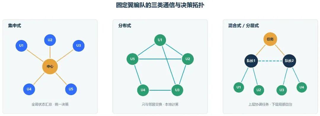
Communication and decision topology describes the source of information and the location of computation nodes — system architecture rather than specific control laws. The same leader–follower method can be computed centrally or independently by each wingman’s onboard computer; MPC also has centralized and distributed versions.
3.1 Centralized: Global Computation Cannot Replace Local Safety
In centralized architecture, a ground station, lead aircraft, or central compute node receives all member states, computes task allocation, trajectories, and control commands uniformly, and sends results to each aircraft. The central node can solve the global problem directly.
Centralized architecture can leverage global information to handle task allocation and inter-vehicle constraints uniformly. However, fixed-wing implementation must also consider the timeliness of downstream commands. Trajectories issued by the central node may already be outdated by the time they reach the aircraft, causing wingmen to chase stale references during continuous forward flight. After the central link breaks, each aircraft must retain local path-keeping, collision avoidance, loiter, or return-to-home capability.
3.2 Distributed: Neighbor Information Must Include Timestamps and Validity
Distributed architecture treats each aircraft as a node in a communication graph. Aircraft i uses its own state and neighbor set information to compute control quantities.
Distributed methods can limit communication and computation burden to local scope and eliminate a single point of central failure. However, fixed-wing aircraft cannot stop when neighbor data is missing. Therefore, each neighbor message must also include a timestamp, state validity period, and prediction information. After topology switching, the new neighbor’s reference trajectory may not be continuous with the aircraft’s current state.
3.3 Hybrid: Low-Frequency Global Coordination with High-Frequency Local Execution
Practical fixed-wing systems typically adopt layered or hybrid architectures: the ground station handles low-frequency mission planning and formation transitions, while formation members perform high-frequency formation keeping, path tracking, and collision avoidance onboard. Large swarms can be divided into sub-teams, with team leaders coordinating within their group and forming an upper-layer network between leaders.
Hybrid architecture suits separating fixed-wing time scales: task allocation and formation reconfiguration at second-level or slower speeds are managed by upper layers; guidance and flight control run at high frequency onboard; when communication is interrupted, a local safety state machine takes over.
| Architecture | Coordination Info Scope | Fixed-Wing Implementation Focus | Minimum Post-Link-Loss Capability | Applicable Scenarios |
|---|---|---|---|---|
| Centralized | Global state | Trajectory delivery latency, central compute cycle, reference continuity | Local path keeping and return-to-home | 2–5 aircraft prototype validation, field tests |
| Distributed | Self and neighbors | Timestamps, topology switching, neighbor trajectory prediction | Local collision avoidance and independent mission | Large-area search, persistent patrol |
| Hybrid | Layered global and local | Upper/lower layer interfaces, state machine and authority switching | Sub-team autonomy or single-aircraft safety mode | Multi-team coordination, engineering swarms |
4. Formation Algorithms: How to Generate Fixed-Wing Flyable References
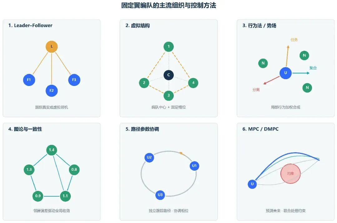
Formation and coordination algorithms determine how each aircraft generates its desired motion. Leader–follower, virtual structure, and behavior-based methods describe formation organization; consensus, vector field, and MPC primarily serve as control or optimization tools. Practical systems can combine multiple methods.
4.1 Leader–Follower: Cannot Track the Leader’s Instantaneous Position Directly
Leader–follower designates one or more lead aircraft to execute the mission route. Wingmen maintain desired offsets based on the leader’s state. If the wingman tracks the leader’s instantaneous position directly, the reference generated after the leader turns may end up behind the wingman’s side, causing the wingman to continuously cut corners or enter speed saturation. Fixed-wing implementation typically uses a virtual leader with look-ahead, leader trajectory prediction, or dynamic slots defined along the leader’s path to keep the reference trajectory continuous.
4.2 Virtual Structure: Rigid Geometry Needs Flyability Correction
The virtual structure method defines a virtual formation center and its attitude, then assigns each aircraft a fixed structural slot position. This method can uniformly generate references for all members without relying on a real leader to continuously provide state.
Fixed-wing formations cannot strictly maintain rigid body characteristics during all maneuvers. When the virtual center turns, different slot positions correspond to different curvatures, speeds, and roll angles. Engineering implementation can add a flyability correction layer after the virtual structure, smoothing slot positions, limiting structural angular velocity, and allowing temporary formation deformation during sharp turns, strong winds, or inconsistent member performance.
4.3 Behavior-Based Methods & Artificial Potential Fields
Behavior-based methods decompose tasks into local rules such as separation, aggregation, velocity alignment, target approach, and obstacle avoidance. These are then combined through weighted synthesis to produce the desired motion.
The synthesized vector from behavior methods gives an ideal motion direction or velocity vector. Fixed-wing aircraft can only adjust their flight path direction gradually through limited roll angle. The desired direction must be converted to desired flight path angle and airspeed, then constrained for path angle rate, minimum airspeed, and path curvature.
4.4 Consensus Methods: Coordination Variables Cannot Default to Position
Consensus methods use neighbor errors to converge position, velocity, heading, arrival time, or path parameters to agreement. For single-integrator models, the consensus protocol can serve directly as velocity input. Fixed-wing aircraft lack an independent lateral velocity channel and cannot apply the same control law directly to 3D position. A more appropriate approach uses consensus on flight path angle, speed, arrival time, or virtual path parameters, with the single-aircraft guidance layer handling spatial path convergence.
4.5 Vector Fields & Path Parameter Coordination: Suitable for Continuous Forward Flight
Vector field methods construct position-dependent desired flight directions for each aircraft, allowing convergence to target paths from arbitrary initial positions. The formation layer does not directly control 3D relative positions — instead it coordinates speed or virtual path parameters so members maintain desired phase offsets along their respective flyable paths.
This layered approach suits fixed-wing forward flight characteristics: the vector field handles spatial path convergence, while the consensus term adjusts only path progress. However, parameter coordination requires sufficient speed adjustment margin for each aircraft.
4.6 MPC & Distributed MPC: Explicit Constraints Depend on Model Accuracy and Real-Time Computation
Model Predictive Control predicts motion over a future horizon at each time step and solves a constrained optimization problem. MPC can handle fixed-wing dynamics, airspeed range, roll angle, formation error, and inter-vehicle safety distance within the same prediction problem. Centralized MPC optimizes the entire formation at once; distributed MPC exchanges predicted trajectories and solves local problems separately.
Recent hardware experiments with 4 agile fixed-wing aircraft flying within ~0.56–0.60 m minimum spacing demonstrate MPC’s potential. However, 3 collisions were also recorded, 1 resulting in airframe loss. This confirms that explicit constraints cannot eliminate model mismatch, low voltage, attitude limits, or re-planning errors.
5. Combining Topology, Algorithms, and Fixed-Wing Constraints
Communication topology, formation organization, and fixed-wing guidance belong to different layers. Selection requires determining not just the algorithm name, but simultaneously the information source, reference type, and flyability handling approach.
| Method | Common Topology | Formation Layer Output | Fixed-Wing Implementation Correction | Primary Risks |
|---|---|---|---|---|
| Leader–Follower | Centralized / Distributed / Hybrid | Dynamic slot or leader reference trajectory | Virtual leader, look-ahead, curvature & speed limits | Leader dependency, turn chasing, error propagation |
| Virtual Structure | Centralized / Hybrid | Formation center and slot trajectories | Angular velocity limits, deformable slots | Slots unflyable during sharp turns |
| Behavioral / Potential Field | Distributed | Desired motion direction or velocity | Flight path angle mapping, rate limits, forward prediction | Local minima, command oscillation |
| Consensus | Distributed / Hybrid | Heading, speed, arrival time, or path parameters | Avoid direct position single-integrator input | Delay, topology switching, speed saturation |
| Vector Field + Parameter Coordination | Distributed / Hybrid | Path direction and virtual progress | Path curvature check, speed margin management | Phase error bounded by speed limits |
| MPC / DMPC | All three | Constrained trajectories or control sequences | Fixed-wing model, real-time solving, tracking error margin | Model mismatch, compute & communication timeout |
| Learning-Enhanced Control | All three | Policy actions, compensation signals, candidate trajectories | Safety filter, flight envelope, failure state machine | Generalization, interpretability, safety verification |
When reading papers or designing systems, confirm in sequence:
- What reference quantity does the algorithm generate at the formation layer?
- Which layer converts the reference into fixed-wing guidance commands?
- Where are turn radius, airspeed, roll angle, and climb rate constrained?
- Is neighbor state from current measurement or predicted trajectory? How are timestamps handled?
- What safety mode does each aircraft enter when the central node or communication link fails?
6. Task-Specific Selection & Validation Sequence
| Mission Objective | Recommended Architecture & Method | Fixed-Wing Priority Validation Items |
|---|---|---|
| Dual / Triple aircraft formation flight | Simple hybrid + Leader–Follower | Leader turns, look-ahead distance, speed saturation, link-loss dissolve |
| Multi-aircraft equidistant patrol along route | Distributed vector field + path parameter consensus | Path curvature, speed adjustment margin, topology connectivity |
| V-formation or diamond tight formation | Hybrid virtual structure + robust tracking | Slot flyability, wind disturbance, positioning error, wake effects |
| Large-area search & coverage | Grouped hybrid + behavioral / consensus | Network partitioning, local conflicts, member dropout |
| High-density close-in maneuvering | Centralized NMPC or DMPC | Model accuracy, real-time solving, predicted trajectory timeliness, collision margin |
When starting fixed-wing formation experiments, it is recommended to first validate individual aircraft path tracking performance, then proceed to dual aircraft leader–follower. Subsequently introduce communication delay, wind disturbance, speed saturation, and link-loss state machines before extending to distributed consensus, dynamic collision avoidance, and formation reconfiguration.
When coordination conditions are no longer satisfied, priority should be given to single-aircraft flight safety, executing formation dissolve, altitude stagger, designated-area loiter, or individual return-to-home strategies. After communication is restored, do not immediately switch back to the original formation — recheck member positions, speeds, and remaining mission, then complete reconfiguration through smooth trajectories.

If you have any questions about fixed-wing formation flight systems or need custom FPV/data link solutions for your formation UAV project, feel free to contact us at [email protected].

7. Summary
Fixed-wing formation flight requires simultaneous analysis of system layering, communication topology, coordination algorithms, and aircraft constraints. Centralized, distributed, and hybrid architectures describe information flow and computation location; leader–follower, virtual structure, behavioral methods, consensus, vector fields, and MPC describe how coordination references are generated.
These general multi-agent methods only produce fixed-wing flyable formation schemes when continuous forward flight, minimum turn radius, airspeed range, roll angle, communication delay, and link-loss handling are incorporated. Algorithm comparison should focus not only on whether position error converges, but also on whether the reference trajectory is flyable, whether communication data is valid, and whether individual aircraft can maintain safety after coordination failure.
Have questions about this article? Feel free to contact us at [email protected] — we’re happy to help!
Frequently Asked Questions
1. What is the minimum communication frequency recommended for fixed-wing formation?
For practical fixed-wing formation, 5–20 Hz data link updates are typically recommended depending on aircraft speed and wing loading. Slower links (1–2 Hz) may be viable if each aircraft carries onboard trajectory prediction. Aomway offers configurable telemetry links suitable for formation flight applications.
2. How many aircraft can practically fly in a fixed-wing formation?
Published field experiments have demonstrated 5–50 aircraft, with team-based hierarchical architectures scaling better. For sub-10 aircraft formations, hybrid leader–follower or virtual structure methods are commonly used. Beyond 20 aircraft, distributed consensus or grouped architectures are recommended.
3. Can Aomway products support formation flight telemetry?
Yes. Aomway video and data transmission systems can be configured to support the bandwidth and latency requirements of formation flight, including real-time FPV feedback from each aircraft and inter-vehicle data relay. Contact us at [email protected] for technical specifications.
4. What happens when one aircraft loses GPS in formation?
This is a critical safety case. The aircraft should immediately transition to a safe mode — either altitude-hold loiter or a pre-planned return-to-home using dead reckoning. The remaining formation should dissolve and re-evaluate before reforming. GPS-denied formation flight requires alternative relative positioning such as vision-based or UWB ranging.
5. What is the biggest engineering challenge for fixed-wing formation?
In our experience, managing communication latency and maintaining trajectory continuity during topology changes are the most common recurring issues. Theoretical convergence proofs often assume instantaneous perfect communication, while real links introduce delay, jitter, and dropout. Aomway recommends validating with hardware-in-the-loop simulation before live flight testing.
