

The self-balancing robot is a classic entry-to-advanced project in the embedded world. It combines sensor data acquisition, motion control algorithms, and motor driver technology, offering outstanding training value for developers in both hardware programming and algorithm design.
This article provides a full walkthrough of an STM32-based self-balancing robot project — from system architecture and software implementation to parameter tuning. The focus is on two core topics: PID parameter tuning and gyroscope raw data processing. Complete source code with detailed comments is included, so developers can quickly understand the control principles and start building their own balancing robot.
At Aomway, we specialize in motion control and wireless video transmission for FPV and robotics platforms — the same disciplines this project exercises. If you are developing a robot or drone product, our engineering team can help you move from prototype to production.
Key Takeaways
- Skip the DMP — processing raw MPU6050 data directly is faster and consumes fewer resources than the vendor DMP library
- Dual-loop PID — an angle loop (tilt correction) plus a speed loop (encoder feedback) keeps the robot stable and responsive
- Tune P, then D, then I — the article shows live on-device tuning via serial commands (A/C adjust P, D/E adjust D, F/B adjust I)
- Full commented source — every module is explained line by line, from MPU6050 driver to PWM output
- Modular architecture — clean separation of sensor, control, display, and communication layers makes the code easy to extend
1. Introduction
The self-balancing robot integrates a six-axis IMU, encoder feedback, and PID control to stand upright on two wheels. It is one of the most instructive embedded projects because it demands real-time performance, careful sensor fusion, and iterative tuning.
This project is built on the STM32 platform and deliberately avoids the DMP (Digital Motion Processor) approach — DMP is slow and resource-hungry. Instead, the code processes raw gyroscope and accelerometer data directly, which improves response speed and gives developers full control over the data pipeline.
2. Software Design
Below is a module-by-module breakdown of the core code. Each block includes detailed comments.
2.1 Header Files and Global Variables

#include "led.h"          // LED driver header
#include "delay.h"        // delay function header
#include "key.h"          // button driver header
#include "sys.h"          // system initialization header
#include "lcd.h"          // LCD display driver header
#include "usart.h"        // UART communication header
#include "mpu6050.h"      // MPU6050 gyroscope driver header
#include "inv_mpu.h"      // official MPU driver header
#include "inv_mpu_dmp_motion_driver.h"  // DMP motion processing driver
#include "oled.h"         // OLED display driver header
#include "pwm.h"          // PWM driver header
#include "function.h"     // custom function header
#include "fuzzy.h"        // fuzzy control algorithm header
#include "time.h"         // timer driver header
#include "FTM.h"          // FTM module driver header
#include "rtu.h"          // RTU communication protocol header

char receive;             // UART received character
float result;             // temporary calculation result
angle ress;               // angle-related struct variable
p_angle res;              // angle control parameter struct pointer
speed_s spe_L;            // left wheel speed struct variable
speed_ss speed_L;         // left wheel speed control pointer
speed_s spe_R;            // right wheel speed struct variable
speed_ss speed_R;         // right wheel speed control pointer
out_b outt;               // output parameter struct variable
out_c out;                // output control pointer
int ab;                   // temporary control variable
float roll;               // roll angle (computed from MPU6050)
int ti=9;                 // speed control variable
float ta;                 // temporary angle variable
int ti_r;                 // right wheel speed temp variable
int ti_l;                 // left wheel speed temp variable
float CN_timer2;          // timer 2 counter variable
float CN_timer3;          // timer 3 counter variable
int time;                 // time-related variable
int32_t rtu_send[6];      // RTU protocol send data array
2.2 Main Function Initialization

int main(void)
{
    float mm=0;           // temporary angle error variable
    int P=64;             // PID parameter - P
    float I=0;            // PID parameter - I
    float D=0.005;        // PID parameter - D
    float i;              // temporary integral variable
    float d;              // temporary derivative variable
    float e;              // temporary error variable
    int integer,point;    // angle integer and decimal parts
    float pitch,yaw;      // Euler angles: pitch, yaw
    short aacx,aacy,aacz; // accelerometer raw data
    short gyrox,gyroy,gyroz; // gyroscope raw data
    short temp;           // temperature variable
    int m;                // temporary loop variable

    // initialize struct pointer links
    out=&outt;
    res=&ress;
    speed_L=&spe_L;
    speed_R=&spe_R;

    // initialize speed parameters
    speed_L->speed_last=0;
    speed_R->speed_last=0;
    ta=0;
    ti=80;
    res->angle_sum=0;     // angle error integral sum
    res->angle_error=0;   // angle error delta
    res->angle_last=0;    // previous angle
    res->angle_now=0;     // current angle
    m=0;

    // hardware module initialization
    delay_init();         // delay init
    OLED_Init();          // OLED display init
    pwm_init();           // PWM motor driver init
    time1_init();         // timer 1 init
    uart_init(115200);    // UART init, 115200 baud
    Hardware_init();      // custom hardware init
    ti=0;
    ab=1000;

    // OLED shows initial state
    OLED_ShowString(40,2 ,"Stop");
}
2.3 Button and Serial Command Handling

    while(1)
    {
        // parameter range limits to prevent overflow
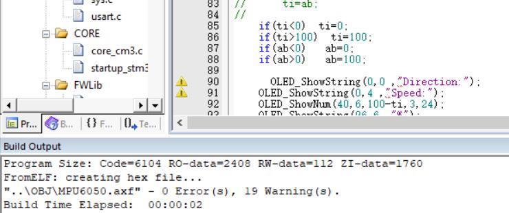
        if(ti<0)  ti=0;
        if(ti>100)  ti=100;
        if(ab<0)   ab=0;
        if(ab>0)   ab=100;

        // OLED shows current state
        OLED_ShowString(0,0 ,"Direction:");
        OLED_ShowString(0,4 ,"Speed:");
        OLED_ShowNum(40,6,100-ti,3,24);
        OLED_ShowString(96,6 ,"%");

        // serial command parsing for motion control
        switch (receive)
        {
            // increase speed
            case 'A':
                ti+=5;
                receive='p'; // reset flag to avoid repeats
                break;
            // decrease speed
            case 'B':
                ti-=5;
                receive='p';
                break;
            // forward
            case 'C':
                forward();
                OLED_Clear();
                OLED_ShowString(40,2 ,"Forward");
                receive='p';
                break;
            // backward
            case 'D':
                back();
                OLED_Clear();
                OLED_ShowString(40,2 ,"Back");
                receive='p';
                break;
            // stop
            case 'E' :
                stop();
                ti=0;
                OLED_Clear();
                OLED_ShowString(40,2 ,"Stop");
                receive='p';
                break;
            // turn left
            case 'F' :
                left();
                OLED_Clear();
                OLED_ShowString(40,2 ,"Turn_left");
                receive='p';
                break;
            // turn right
            case 'G' :
                right();
                OLED_Clear();
                OLED_ShowString(40,2 ,"Turn_right");
                receive='p';
                break;
            // move up (for robots with a lift mechanism)
            case 'H' :
                up();
                ti=50;
                OLED_Clear();
                OLED_ShowString(40,2 ,"up");
                receive='p';
                break;
            // move down
            case 'I' :
                down();
                ti=50;
                OLED_Clear();
                OLED_ShowString(40,2 ,"down");
                receive='p';
                break;
            // decrease parameter
            case 'J' :
                ab-=5;
                OLED_Clear();
                receive='p';
                break;
            // increase parameter
            case 'K' :
                ab+=5;
                OLED_Clear();
                receive='p';
                break;
        }
}
2.4 Sensor Data Processing and PID Control

        // hardware and communication module init
        Hardware_init();
        uart_init(115200);
        usart_init_();
        time1_init();
        Encoder_Init_TIM2();  // encoder timer 2 init
        Encoder_Init_TIM3();  // encoder timer 3 init

        // MPU6050 init, show message on failure
        while(mpu_dmp_init())
        {
            OLED_ShowString(0,2 ,"MPU6050 initting");
        }
        OLED_Clear();

        // PID parameter initialization
        res->angle_P=81;     // angle loop proportional gain
        res->angle_I=0.001;  // angle loop integral gain
        res->angle_sum=0;    // angle error integral sum
        res->angle_D=18;     // angle loop derivative gain
        mm=0;

        // OLED UI initialization
        OLED_ShowString(0,2 ,"roll:");
        OLED_ShowString(2,0 ,"L:");
        OLED_ShowString(60,0 ,"R:");
        OLED_ShowString(100,2 ,".");
        OLED_ShowString(0,6 ,"P:");
        OLED_ShowString(46,6,"I:");
        OLED_ShowString(90,6 ,"D:");

        while(1)
        {
            // PID tuning command parsing
            switch (receive)
            {
                // increase angle P parameter
                case 'T':
                    ta=ta+1;
                    receive='p';
                    break;
                // decrease angle P parameter
                case 'J':
                    ta-=1;
                    receive='p';
                    break;
                // increase angle P
                case 'A':
                    res->angle_P+=1;
                    receive='p';
                    break;
                // decrease angle P
                case 'C':
                    res->angle_P-=1;
                    receive='p';
                    break;
                // increase angle D
                case 'D':
                    res->angle_D+=1;
                    receive='p';
                    break;
                // decrease angle D
                case 'E':
                    res->angle_D-=1;
                    receive='p';
                    break;
                // increase angle I
                case 'F' :
                    res->angle_I+=0.001;
                    receive = 'p';
                    break;
                // move backward and decrease angle I
                case 'B':
                    back();
                    res->angle_I-=0.001;
                    break;
                // stop
                case 'S':
                    stop();
                    receive = 'p';
                    break;
                // increase speed
                case 'M':
                    ti+=1;
                    receive = 'p';
                    break;
                // decrease speed
                case 'N':
                    receive = 'p';
                    ti-=1;
                    break;
            }
}
2.5 Angle Calculation and Motor Control

            // get Euler angles computed by MPU6050
            if(mpu_dmp_get_data(&pitch,&roll,&yaw)==0)
            {
                // get accelerometer raw data
                MPU_Get_Accelerometer(&aacx,&aacy,&aacz);
                // get gyroscope raw data
                MPU_Get_Gyroscope(&gyrox,&gyroy,&gyroz);

                // scale roll angle x10 for easier processing
                temp=roll*10;
                // handle sign display
                if(temp<0)
                {
                    OLED_ShowString(50,2 ,"-");
                    temp=-temp;
                } else
                    OLED_ShowString(50,2 ,"+");

                // split integer and decimal parts for display
                integer = temp/10;
                point   = temp%10;

                // PID algorithm computes output PWM value
                time=(2000-(res->angle_P*mm+res->angle_I*res->angle_sum-res->angle_D*res->angle_error));
                // clamp minimum output to keep motors spinning
                if(time<1)
                {
                    time=1;
                }

                // control motor direction based on angle error
                if(res->angle_now<0)
                {
                    forward();       // move forward
                    mm=-res->angle_now;
                }
                else
                {
                    back();          // move backward
                    mm=res->angle_now;
                }

                // OLED display: angle, PID parameters, etc.
                OLED_ShowNum(60,2,integer,3,18);
                OLED_ShowNum(108,2,point,1,8);
                OLED_ShowNum(12,6,(res->angle_P),3,18);
                OLED_ShowNum(60,6,(res->angle_I)*1000,3,18);
                OLED_ShowNum(102,6,res->angle_D,3,18);
                OLED_ShowNum(0,4,mm,3,18);

                // display angle error delta
                if(res->angle_error<0.5)
                {
                    OLED_ShowString(68,4 ,"-");
                    OLED_ShowNum(76,4,-res->angle_error,4,20);
                }
                else
                {
                    OLED_ShowString(68,4 ,"+");
                    OLED_ShowNum(76,4,res->angle_error,4,20);
                }

                // prepare RTU send data
                rtu_send[0]=res->angle_now*100;
                rtu_send[1]=2000-time;
                // send data to host via RTU protocol
                rtu_send_data(rtu_send,2);
                rtu_send_data(rtu_send,2);

                // OLED shows motor PWM values
                OLED_ShowNum(20,0,time,4,20);
                OLED_ShowNum(80,0,time,4,20);

                // indicator LED blinks to show system running
                while(1)
                {
                    GPIO_ResetBits(GPIOC,GPIO_Pin_13);
                    delay_ms(1000);
                    GPIO_SetBits(GPIOC,GPIO_Pin_13);
                    delay_ms(1000);
                }
            }
        }
}
3. Design Analysis
3.1 Hardware Selection
- MCU — the STM32 series offers rich peripherals and strong compute performance, fully capable of real-time balancing control
- IMU — the MPU6050 six-axis sensor integrates an accelerometer and gyroscope, capturing both attitude and motion data
- Drive — PWM-controlled DC motors with encoder-based closed-loop speed control
3.2 Software Architecture
- Modular design — clean code structure that simplifies extension and debugging
- Dual-loop PID — an angle loop plus a speed loop ensures both balance accuracy and motion stability
- Raw gyroscope processing — bypassing the DMP reduces resource usage and improves response speed — the same design philosophy Aomway applies when optimizing flight controllers and gimbal control for our FPV platforms
3.3 Possible Improvements
- Add Bluetooth/WiFi for remote control via a mobile app
- Integrate vision modules for autonomous obstacle avoidance and path planning
- Implement auto-tuning PID algorithms to reduce manual tuning effort
4. Summary
This article breaks down the core technology of an STM32 self-balancing robot, from hardware architecture to software implementation, with a focus on PID tuning and gyroscope raw data processing.
Thanks to the modular code design and detailed comments, developers can quickly grasp the control principles and extend the project to suit their own needs. Whether you are new to embedded development or an experienced engineer, this project is a practical way to learn motion control algorithms and sensor data processing.
At Aomway, motion control is what we do every day — from FPV gimbals and VTX systems to robotics test platforms. If you are working on a balancing robot, drone, or any motion-sensitive embedded system, feel free to reach out to our engineering team.
5. Resources
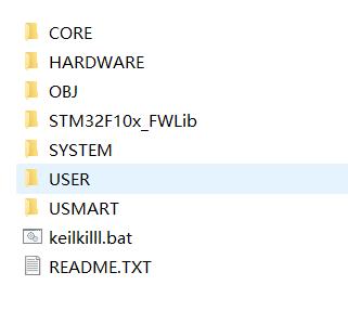
The complete source code package (with detailed comments) is available for download. The project includes all driver modules referenced above, ready to port to your own STM32 board.

If you have any questions about this topic, feel free to contact us at [email protected]
Have questions about this article? Feel free to contact us at [email protected] — we’re happy to help!
