

This article introduces a phased array antenna that can synthesize arbitrary radiation patterns, combining both electronic and physical improvements to achieve this goal.
The Need for Adaptive RF Circuits
Fixed RF systems are not the best choice for dealing with changing RF environments. Ideally, RF modules should be context-aware and capable of adjusting for optimal overall system performance. In the past, reconfigurability meant mounting components such as antennas on large servo motors and moving them to point at signal sources. In fact, radio astronomers still build large parabolic antennas on railroad tracks and move them to adjust various configurations, receiving faint signals from space. But for modern applications, this approach is usually far too slow.
Engineers quickly realized that phased array antennas could achieve the same beam-steering effect electronically. Instead of moving the antenna, they adjust the phase differences between individual elements. Constructive and destructive interference between array elements helps steer the radiated beam without physically moving the antenna. Since everything is electronic, controlling the antenna direction takes only a few microseconds.
What if we could combine physical deformation with electronic beam steering? Foldable phased array antennas are an excellent application for this, because they allow slow, origami-like physical deformation, followed by fast electronic beam steering. Can we create any desired antenna pattern and then steer the beam?
The Egg-Crate Phased Array
The phased array antenna design from the Georgia Tech research paper takes its inspiration from a paper egg carton. It is essentially a grid of inverted square pyramids that are open at the bottom to hold eggs. The research describes how these open-bottom pyramids can serve as the basis for a larger reconfigurable array. Looking at one pyramid in isolation, its unit structure resembles the origami fortune tellers my kids love to fold.
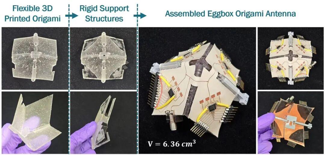
Unit cell construction of the egg-crate/fortune-teller phased array. Source: Hani Al Jamal, Georgia Tech.
Each of the four faces of the egg-crate/fortune-teller device carries a 4-element phased array antenna, with beams controlled by a Qorvo AWMF-0108 28 GHz beamformer RFIC in 11.25° increments.
This unit structure resembles an origami design and can be folded or flattened along either axis, enabling physical changes to the radiation direction. Since the phased array on each face can further steer the beam, combining physical folding with electronic beam steering lets this antenna generate almost any radiation pattern.
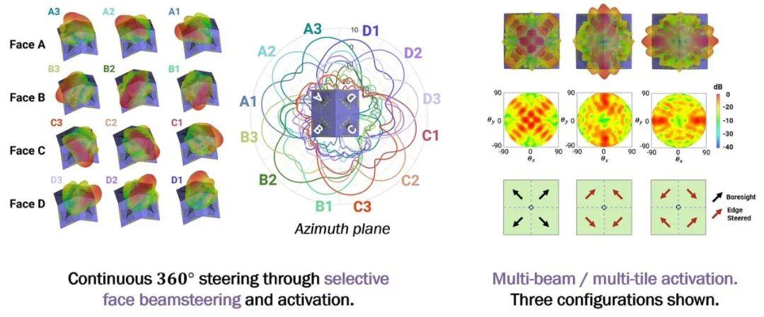
Here are some ways to shape this antenna’s radiated beam:
- 360° azimuth coverage: in the pyramidal arrangement, activate only one phased array at a time with the beam pointed at maximum, then switch to the phased array on the next face. This ensures continuous switching among multiple phased arrays on different faces while achieving 360° azimuth beam steering.
- Bending along an axis: fold the array along either axis; as the fold angle decreases, the radiation pattern changes from a four-beam configuration to a two-beam configuration, as shown.
- Arbitrary-shaped beams: fold the array at any angle along either axis, activating anywhere from one to all four phased arrays, and apply digital weights to control the amplitude and phase of the antenna elements (even gain tapering to suppress grating lobes). This way you can synthesize almost any radiation pattern you want.
The Interconnect System
When you see a foldable circuit operating at 28 GHz, the first thing that comes to mind is the RF performance and stability of foldable interconnects after repeated folding. Any experienced RF engineer who has worked in a lab knows that RF cables should not be bent. Yet in origami-based circuit design, that is exactly what is required.
To solve this, the authors devised a novel approach using an arched hinge interconnect structure manufactured via 3D printing with flexible photosensitive resin (Flexible 80A). The connector is a 50Ω transmission line fabricated by inkjet printing on a Rogers RO3003 substrate, paired with a 3D-printed support structure. The resulting hinge design is stable and reliable, maintaining low loss across a 180° fold range, with no performance degradation after 300 folding cycles.
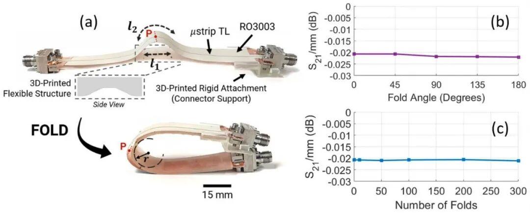
Foldable arched hinge interconnect. Source: IEEE [1]
Another challenge in building the egg-crate unit interconnects is that the feed point can only be located on one face of the 3D structure. This means the interconnect system cannot feed the four phased arrays of the structure symmetrically2. To compensate for the difference in overall electrical length, additional transmission line segments were added in the βl adjustment shown below.
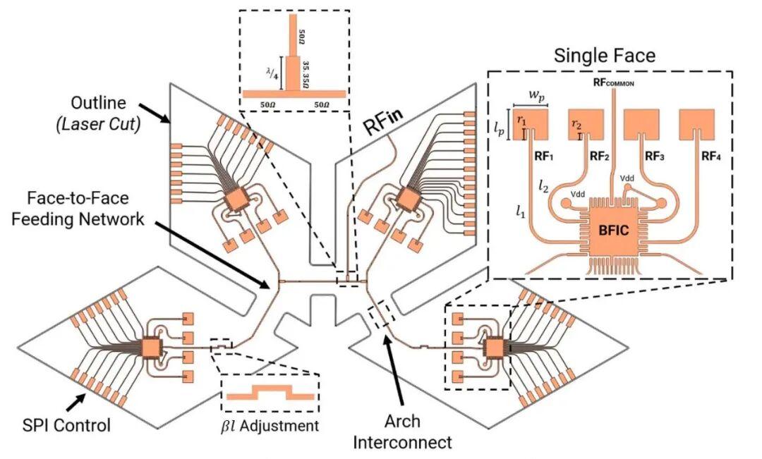
Detailed design of the egg-crate unit. Source: IEEE [1]
Practical Applications
Egg-crate units can be cascaded to build larger arrays and spatially adjusted along either axis — that is what makes the design so attractive. The modular design approach offers other advantages:
- If a single unit cell fails, it can be easily replaced.
- Specific faces of the egg-crate array can be activated based on power usage and transmit/receive operating modes, producing a variety of radiation patterns.
- Additive 3D printing processes generate less waste.
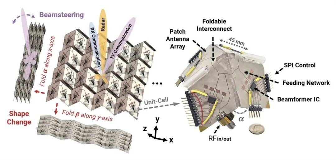
Building larger arrays with egg-crate units. Source: Hani Al Jamal, Georgia Tech.
Let us look at some effective ways to use this phased array antenna:
- Full-duplex operation: to transmit and receive simultaneously with the same array, the modular design allows activating all phased arrays on one side for transmission while using the other side for reception. The electronically steered beams enable tracking targets when necessary.
- Multi-beam operation: as we have seen, two or four beams can be synthesized from the array using different fold angles. In autonomous vehicles, for example, each beam could be assigned a specific role such as communication, navigation, or obstacle avoidance.
- Adjustable beamwidth: since the fold angle determines beamwidth, unfolding the array to produce a wide beam supports aircraft search operations, while folding produces a narrower beam that helps focus rescue missions.
- Space-constrained systems: with compact, low-cost spacecraft like CubeSats becoming more common, the ability to fold the antenna array at launch and deploy it in orbit is especially valuable. Reshaping the array and steering beams in space will help build satellite mesh networks that enhance global connectivity.
This origami-inspired antenna implementation has only two degrees of freedom, but it lays the foundation for future developments with even more degrees of reconfigurability.
The ability to freely adjust radiated beams is crucial to the future of wireless communication, whether in 5G, 6G, automotive radar, aerospace, or military applications.
If you enjoy paper-review articles like this one, please reply to let us know so we can write more. If you find interesting articles with great ideas or novel implementations, share them with us and we will explore them in future briefings.
Reference
[1] H. A. Jamal, C. Hu, N. Wille, K. Zeng and M. M. Tentzeris, “Beyond Planar: An Additively Manufactured, Origami-Inspired Shape-Changing, and RFIC-Based Phased Array for Near-Limitless Radiation Pattern Reconfigurability in 5G/mm-Wave Applications,” in IEEE Microwave and Wireless Technology Letters, vol. 34, no. 6, pp. 841-844, June 2024, doi: 10.1109/LMWT.2024.3396026.
If you have any questions about this topic, feel free to contact us at [email protected]
Have questions about this article? Feel free to contact us at [email protected] — we’re happy to help!
