
Key Takeaways
- Link-22 is the replacement for Link-11, standardized as STANAG 5522, and it was never intended to replace Link-16 – the two operate as a near/far pair.
- Its defining technical break from earlier links is D-TDMA (dynamic time division multiple access) with distributed network control, eliminating the single master node that made Link-11 fragile.
- Two waveforms share one baseband: HF (2-30 MHz skywave) for beyond-line-of-sight at up to roughly 1200 bps, and UHF (225-400 MHz line-of-sight) at up to roughly 12.8 kbps. Both use 4-CPFSK.
- Variable-length F-series messages exist specifically to avoid wasting bandwidth on low-rate HF channels, and an F/J gateway bridges them to Link-16’s fixed-length J-series.
- The engineering core is not the hardware – it is baseband waveform software, distributed SNC scheduling, cross-link delay compensation, and gateway situation consistency.
When people discuss NATO tactical data links, attention usually goes to Link-16. Link-22, as the replacement for Link-11, fills the long-range wide-area situational awareness gap using HF and UHF dual waveforms, D-TDMA dynamic networking, and distributed network control. This article starts from the program background and then works down through the physical, MAC, network, and message layers, closing with an engineering view of the technical trade-offs and inherent limits.
Background: Why Link-22 Was Developed
The Limits of the Earlier Links
Link-11 was NATO’s long-serving naval long-range data link, built on a master-slave roll call mechanism. The entire network depended on the master node, so losing it meant losing the network. Time slots were statically planned, bandwidth utilization was poor, messages used a fixed block structure that wasted capacity, and HF and UHF operated as independent single links with no dynamic routing. By the 1990s it could no longer meet the needs of modern blue-water formations or multi-formation joint operations.
Link-16 uses line-of-sight L-band and performs strongly, but it cannot natively go beyond line of sight. Long-range use requires airborne relays, and in a contested ocean environment the relay platform is itself a high-value, fragile node.
Launching the NILE Program
NILE stands for NATO Improved Link Eleven. It was launched in the 1990s by the United States, United Kingdom, France, Germany, Italy, Canada, and Spain, with the goal of:
- Fully replacing the aging Link-11
- Achieving integrated HF plus UHF dual-waveform networking
- Adopting a distributed, centerless architecture to improve network survivability
- Remaining compatible with Link-16 message semantics, with situational awareness shared through a gateway
- Supporting automatic relay and dynamic bandwidth scheduling for cross-ocean, cross-region situational sharing
After years of development and at-sea trials, Link-22 was formalized as STANAG 5522 and progressively fielded on NATO surface ships, antisubmarine patrol aircraft, and shore-based command and control nodes.
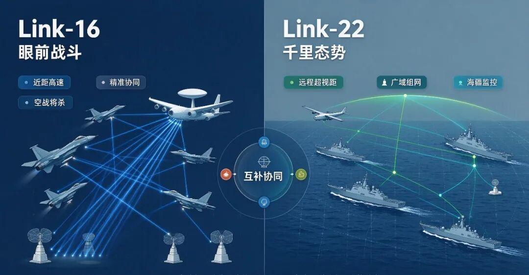
The division of labor is the key to understanding it. Link-16 handles high-density tactical coordination within line of sight. Link-22 handles long-range, cross-region situational exchange where satellite and airborne relay support is unavailable.
Link-16 manages the fight in front of you – short range, high speed, precise coordination, aimed at air combat. Link-22 manages the picture a thousand miles wide – long range, beyond line of sight, wide-area networking, aimed at maritime domain monitoring.
Overall Technical Framework: A Layered Protocol Stack
Link-22 is a complete tactical message exchange protocol stack, layered from the bottom up as: physical layer (waveforms), MAC layer (D-TDMA plus distributed SNC), network layer, F message layer, and application layer (the TDS tactical data system).
The design principle is decoupling the upper protocols from the underlying channel. The same network and message logic can run over an HF skywave or a UHF line-of-sight channel, the network layer selects routes on its own, and the operational system above never needs to be aware of the transmission medium.
Physical Layer: HF and UHF, One Baseband, Two RF Paths
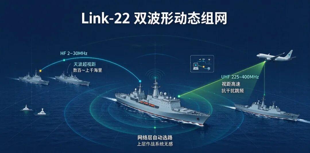
Link-22 defines two independent waveforms. Both use 4-CPFSK (continuous phase frequency shift keying) modulation, share the baseband DSP, and use separate RF channels.
HF Waveform (2-30 MHz, Skywave BLOS)
Propagation: ionospheric reflection for skywave transmission, covering hundreds to over a thousand nautical miles without depending on relay aircraft.
Coding and fading resistance: convolutional coding plus time-depth interleaving to counter ionospheric multipath and short burst errors.
Operating modes: fixed frequency and EPM frequency hopping.
Rate steps: 75/150 bps for weak signal-to-noise long-range links, up to roughly 1200 bps.
Inherent weaknesses: the channel is affected by solar activity, day and night, and season, so delay, Doppler, and multipath vary dynamically. Bandwidth is extremely limited and only suits short tactical messages.
UHF Waveform (225-400 MHz, Line of Sight)
Propagation: line of sight with sea-surface multipath, no skywave.
EPM frequency hopping: faster hopping than HF, giving better antijam and low-probability-of-intercept performance.
Rate: up to roughly 12.8 kbps, used for high-speed situational exchange at short range within a formation.
The physical layer presents a unified frame interface upward while continuously collecting link quality indicators (CQI, error statistics) and reporting them to the SNC, which uses them for slot scheduling and route selection.
MAC Layer: The Core Innovation – D-TDMA Plus Distributed SNC
Link-11 used polling master-slave operation. Link-16 uses static fixed-slot TDMA. Link-22 uses D-TDMA, dynamic time division multiple access. This is the most fundamental technical difference from its predecessors.
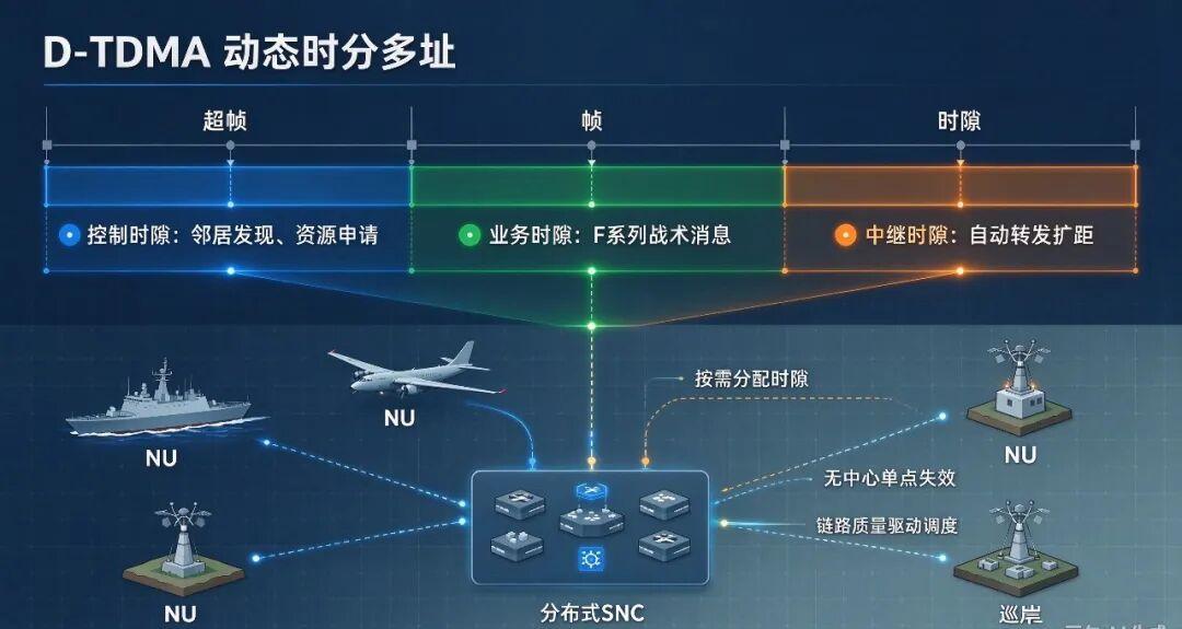
Time Frame Structure
The time domain is divided into superframes, frames, and slots. Slots fall into three categories:
- Control slots: network management messages such as neighbor discovery, link quality reporting, slot resource requests, and node status
- Traffic slots: carrying F-series tactical messages including tracks, command and control, and electronic warfare intelligence
- Relay slots: used for automatic message relay forwarding to extend network coverage
Nodes submit bandwidth requests to the SNC during control slots, and the SNC dynamically allocates slot resources within the next superframe based on link quality and traffic priority. Nothing is pre-allocated; bandwidth is scheduled on demand.
Distributed SNC (System Network Controller)
The SNC is not a dedicated piece of hardware. Every network unit (NU) contains SNC logic. The network elects an Active SNC through distributed negotiation, and if the active SNC fails, other nodes automatically compete for the role. There is no single point of failure.
Core SNC responsibilities:
- Neighbor discovery: maintaining separate HF and UHF adjacency tables
- Link quality assessment: combining physical layer signal-to-noise ratio and error rate to evaluate reachability on both channels
- D-TDMA slot scheduling: responding to bandwidth requests and allocating traffic and relay slots
- Automatic relay management: deciding whether to enable relaying and selecting appropriate relay nodes
- Subnet and supernetwork management
An NU (Network Unit) is the smallest element that can join a Link-22 network – a ship, a patrol aircraft, or a shore station. A single network supports up to 125 NUs.
Supernetwork Mechanism
A single NU can join up to four independent NILE subnets simultaneously. Each subnet has its own D-TDMA timing, and the four can be combined into a logical supernetwork.
Subnets can operate in isolation to preserve formation separation, cross-subnet message forwarding supports multi-formation situation fusion, and a local subnet failure does not bring down the whole supernetwork.
Link-Layer Automatic Relay
Messages are received, decoded, and retransmitted at the link layer, unlike layer-3 IP routing. The SNC triggers relay forwarding automatically based on link quality, filling HF skywave blind spots. Compared with Link-16, there is no need for pre-mission manual planning of relay platforms, which is a significant improvement in network adaptivity.
Network Layer: A Tactical Message Switching Network, Not IP
Link-22 is not an IP network. It is a dedicated message-switching network oriented toward tactical messages.
Addressing: 15-bit NU addresses, compatible with Link-16’s JTIDS address design to lower gateway development cost; 19-bit track numbers, all in WGS-84 coordinates for easier situation fusion.
Cross-channel dynamic routing: the same tactical message can be routed over HF or UHF as conditions favor. Short range prefers UHF; long range and beyond line of sight automatically switch to HF.
Reliability mechanisms: critical tactical messages support link-layer ACK and timeout retransmission, while non-critical situational messages can disable ACK to conserve scarce HF bandwidth.
Message Layer: F-Series Variable-Length Messages and F/J Gateway Interoperability
Link-16 uses fixed-length J-series messages. Link-22 uses variable-length F-series messages, a design specifically adapted to the low-bandwidth HF environment.
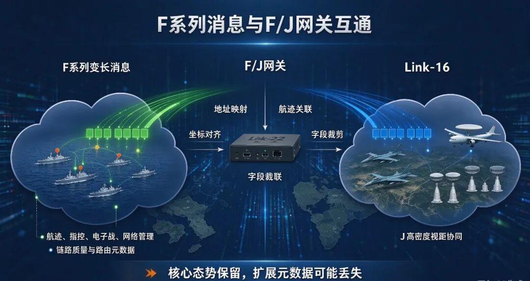
Variable-length messages: a simple track report stays short and lean while a complex command and control message can extend its fields, avoiding the bandwidth waste that fixed-length messages cause on low-rate channels.
Added fields: beyond J message semantics, F messages add quality of track (QoT), routing markers, and relay metadata – fields specific to beyond-line-of-sight networking.
Typical F messages: F1 track messages (the most important), F2 command and control messages, F3 electronic warfare intelligence, and F4 network management messages.
F to J gateway conversion: the gateway node joins both the Link-16 and Link-22 networks and performs address mapping, coordinate alignment, and F to J message conversion.
The technical limitation: Link-22’s unique routing, relay, and link quality fields cannot be mapped into J messages. The conversion loses extended metadata and can only preserve core situational information such as tracks and identification friend or foe. Lossless conversion is not achievable.
Application Layer: The TDS Tactical Data System
The TDS is the operational end of the data link – the mission system aboard a ship or aircraft.
It collects radar, sonar, and electronic surveillance sensor output, generates tactical events, and packages F messages for the data link processor (DLP). It receives remote F messages, performs track correlation and fusion, and builds the local composite situation picture. It provides situation display, human-machine interaction, and combat rule resolution.
The hardware path runs: TDS, to DLP (F message encoding and decoding), to SNC network control logic, to the HF/UHF baseband and RF front end.
Engineering Implementation: From Standard Text to Shipboard Fitting
STANAG 5522 defines the Link-22 protocol specification, but going from paper standard to shipboard and airborne engineering implementation requires solving a large set of hardware, timing, synchronization, and channel adaptation problems. Implementation breaks into five modules: hardware platform, baseband waveform, D-TDMA network control software, message processing and gateway, and system integration and calibration.
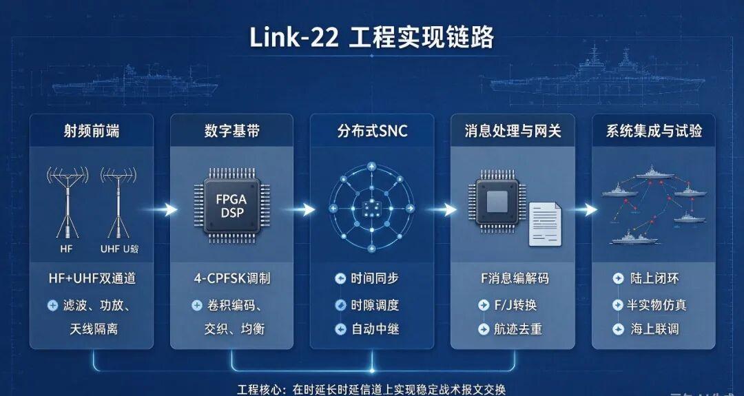
Hardware Platform Architecture
A single Link-22 network unit has four parts:
RF front end: two independent RF channels, an HF channel (2-30 MHz) and a UHF channel (225-400 MHz), each with its own antenna, amplifier, and filters. HF antennas are physically large, and shipboard installation must account for hull blockage and antenna coupling.
Digital baseband DSP/FPGA: a shared baseband processing platform that switches between HF and UHF waveforms by software configuration. The FPGA handles modulation and demodulation, convolutional coding and decoding, interleaving, and hopping sequence generation; the DSP handles link quality assessment and SNC network control algorithms.
Data link processor (DLP): an embedded processor responsible for F-series message encoding and decoding, message validation, time stamp processing, and F/J gateway conversion logic.
Interface unit: interaction with the shipboard TDS, typically Ethernet or a dedicated tactical interface, exchanging situational data in both directions.
The engineering characteristic is shared hardware with software-defined waveforms. The same hardware, loaded with different waveform parameters, switches between HF and UHF operation, reducing shipboard hardware retrofit cost.
Physical Layer Implementation Points
Modulation and demodulation: unified 4-CPFSK with coherent demodulation in the FPGA. The HF channel suffers severe multipath fading, so built-in channel equalization is mandatory.
Channel coding: convolutional codes plus block interleaving. Interleaving depth is the key engineering trade-off: deeper interleaving resists burst errors better but adds delay, which is unfriendly to real-time command and control traffic.
EPM frequency hopping: two pseudo-random sequences, one for HF and one for UHF. HF hopping has narrow bandwidth and a low hop rate; UHF hopping is faster and more jam-resistant.
Link quality (CQI) collection: continuous statistics on SNR, bit error rate, and multipath delay feed the SNC scheduler. The HF channel varies with the ionosphere across day and night, so CQI needs dynamic smoothing to prevent short-term jitter from causing frequent slot reallocation and network oscillation.
MAC Layer D-TDMA and Distributed SNC: The Hardest Part
Link-16’s static slots require only simple clock synchronization in engineering terms. Link-22’s distributed D-TDMA is the most complex part of the implementation.
Network-wide time synchronization: all NUs maintain a common superframe timing. External timing (GPS) is possible, and network-internal self-synchronization is supported without GPS. Long-range HF links carry significant propagation delay, so delay compensation is mandatory; the large delay difference between HF skywave and UHF line of sight is the dominant source of synchronization error.
Distributed SNC negotiation and election: every NU runs the full SNC software. At network startup an Active SNC is elected by negotiation, and re-election is triggered automatically when the active SNC is lost or its link quality degrades. The engineering difficulty is that distributed negotiation involves message propagation delay, which can produce inconsistent state and split-brain risk, requiring anti-conflict mechanisms.
Slot requests and resource allocation: nodes report traffic demand, priority, and neighbor link quality during control slots, and the Active SNC computes and distributes the slot allocation table within the next superframe. The engineering trade-off is that the scheduling algorithm cannot be too complex – sophisticated optimization brings heavy computational cost, and embedded platforms have limited capacity, so lightweight heuristic scheduling is required.
Automatic relay logic: the SNC selects relay nodes automatically from the CQI adjacency table. Messages are decoded and forwarded at the link layer, not simply RF-amplified. Relay depth must be controlled in engineering terms: more hops mean higher cumulative delay and heavy consumption of slot resources.
Message Layer and F/J Gateway Implementation
F-series variable-length codec: the DLP handles message packaging, field validation, time stamps, quality of track, and insertion of relay markers. Variable-length messages bring fragmentation and reassembly problems, and on a low-rate HF link a lost fragment invalidates the entire message.
F to J gateway implementation: maintaining an address mapping table between 15-bit NU addresses and Link-16 JTIDS addresses; unifying coordinates in WGS-84 with track number mapping and time alignment; field trimming, since F-specific relay markers and link quality metadata cannot be written into fixed-length J messages and the gateway can only discard the extended fields; and track de-duplication, because the same target may arrive as a track from both Link-16 and Link-22, so the gateway must correlate and de-duplicate or the situation picture shows duplicate targets.
The engineering pain point is that the two sides of the gateway have different network time bases, producing track time misalignment and target position jumps during situation fusion.
System Integration, Calibration, and Sea Trials
Multi-NU integration: land-based closed-loop testing followed by multi-ship sea trials. The maritime environment brings hull vibration, antenna mutual interference, sea-surface multipath, and time-varying ionospheric interference that differ substantially from laboratory simulation models.
Electromagnetic compatibility: with HF and UHF antennas operating simultaneously, RF isolation is a major shipboard integration challenge and self-interference is easy to produce.
Simulation versus fitted equipment: the usual engineering path is to complete D-TDMA and HF channel simulation on a platform such as AFSIM first, then move to hardware-in-the-loop simulation, and finally iterate parameters during sea trials.
Inherent Engineering Constraints
- HF bandwidth bottleneck: no amount of hardware optimization escapes the shortwave bandwidth limit. Only condensed tactical messages fit – raw sensor data and imagery cannot be carried.
- Synchronization overhead: D-TDMA control slots, neighbor discovery, and SNC negotiation consume bandwidth, and management overhead grows with the number of nodes.
- Robustness under electromagnetic attack: HF is easier to direction-find and jam, so EPM frequency hopping, power control, and message priority mechanisms are used to reduce the risk of being suppressed.
Summary of the core conflict: Link-22’s engineering challenge is achieving distributed dynamic slot scheduling and reliable tactical message exchange over an HF channel that is time-varying, low-rate, and long-delay. The standard defines what Link-22 should do; the engineering implementation determines whether it can actually run stably in the complex electromagnetic environment of the open ocean. Hardware is only the carrier – the real core lies in embedded software: baseband waveform processing, distributed SNC scheduling algorithms, cross-link delay compensation, and gateway situation consistency handling.
Technical Trade-Offs: Where Link-22 Falls Short
Every communication architecture is the result of trade-offs, and Link-22 has clear limitations:
- HF channel rates are low, only at the kbps level, so imagery, video, and large volumes of raw sensor data cannot be transmitted – only condensed tactical messages.
- The HF skywave channel is strongly time-varying, and ionospheric disturbance brings delay jitter and signal fading.
- The HF band is more exposed to electronic surveillance, direction finding, and targeted jamming; its low-probability-of-intercept performance is weaker than Link-16’s L-band high-speed hopping.
- D-TDMA distributed scheduling, multi-node time synchronization, and HF link quality assessment algorithms are highly complex, making engineering implementation and simulation modeling difficult.
Conclusion
Link-22 is not a replacement for Link-16. It is a key foundation of the wide-area, long-range situational layer in NATO system-of-systems operations.
Link-16 is strong at high-density, high-maneuver platform coordination within line of sight. Link-22, relying on HF/UHF dual waveforms, D-TDMA dynamic slots, distributed network control, supernetwork architecture, and automatic relay, solves long-range situational exchange across the ocean.
In high-intensity scenarios where satellite communication is suppressed, Link-22 can serve as the fallback tactical communication means for a naval formation. Understanding Link-22’s layered technical design is what makes the underlying logic of the “near and far data link pair” in NATO maritime and air operations legible.
Link-11 vs Link-16 vs Link-22
| Attribute | Link-11 | Link-16 | Link-22 |
|---|---|---|---|
| Multiple access | Master-slave roll call | Static fixed-slot TDMA | D-TDMA dynamic |
| Waveforms | HF or UHF, independent | L-band line of sight | HF and UHF integrated |
| Beyond line of sight | HF skywave | Requires airborne relay | Native HF skywave |
| Network control | Central master node | Static | Distributed SNC, no single point of failure |
| Message format | Fixed block structure | J-series, fixed length | F-series, variable length |
| Typical rate | Low | High, line of sight | ~1200 bps HF, ~12.8 kbps UHF |
| Scale | Limited | Large within line of sight | 125 NU per network, 4 subnets per NU |
Have questions about this article? Feel free to contact us at [email protected] — we’re happy to help!
Frequently Asked Questions
Does Link-22 replace Link-16?
No. Link-22 was designed to replace Link-11, not Link-16. The two operate as a near and far pair: Link-16 handles high-density line-of-sight tactical coordination, while Link-22 handles long-range, beyond-line-of-sight situational exchange.
What is D-TDMA and why does it matter?
D-TDMA is dynamic time division multiple access. Unlike Link-16’s static fixed slots or Link-11’s master-slave polling, it allocates bandwidth on demand from a distributed controller, which removes the single point of failure and improves bandwidth utilization.
What are the two Link-22 waveforms?
An HF waveform from 2 to 30 MHz using ionospheric skywave for beyond-line-of-sight links at up to roughly 1200 bps, and a UHF waveform from 225 to 400 MHz for line-of-sight links at up to roughly 12.8 kbps. Both use 4-CPFSK modulation.
Why does the F to J gateway lose information?
F messages carry fields specific to beyond-line-of-sight networking, including routing, relay markers, and link quality metadata. J messages are fixed length and have no place for them, so the gateway discards those fields and preserves only core situational data.
What is the main engineering difficulty in Link-22?
Running distributed dynamic slot scheduling reliably over an HF channel that is time-varying, low-rate, and long-delay. Time synchronization, SNC election without split brain, and cross-link delay compensation are the hardest problems.
About Aomway
Aomway is a technology company specializing in drone and FPV equipment, publishing in-depth analyses of motor control, embedded hardware, and open-source robotics projects. With over 15 years of industry experience, Aomway covers the full spectrum from flight controllers and FPV goggles to thermal imaging cameras and long-range datalinks for the global drone community.