

Key Takeaways
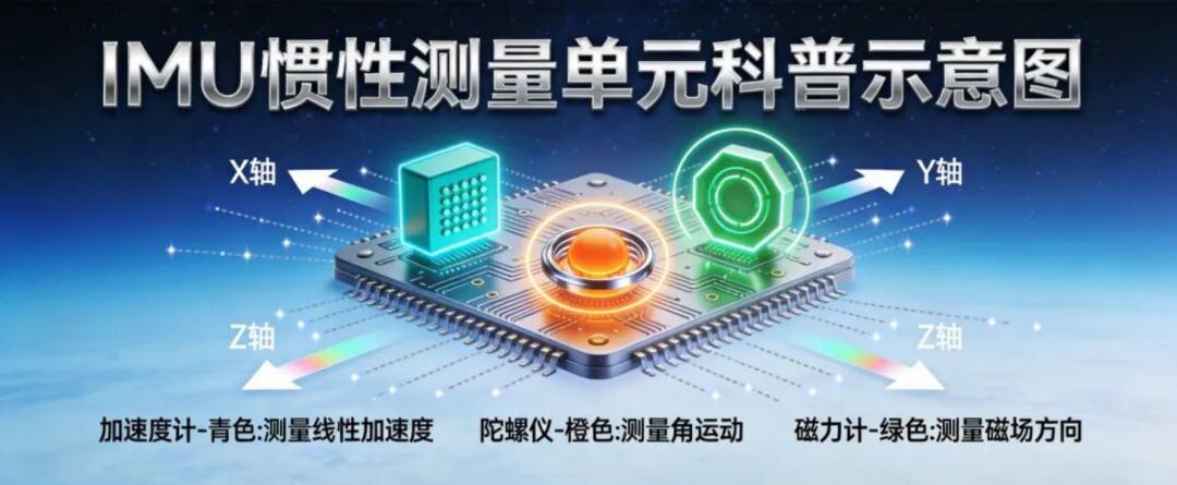
- A MEMS IMU pairs three accelerometers with three gyroscopes, sensing acceleration and rotation on the X, Y and Z axes.
- Accelerometers measure “push”, not speed: a sensor at rest and one moving at constant velocity read identically.
- Gyroscopes use the Coriolis effect to turn rotation into a measurable vibration proportional to angular rate.
- Gyro drift grows without bound because angle is the integral of rate; a magnetometer adds a non-drifting absolute reference.
- Quaternions avoid the gimbal lock and 360° wraparound that break Euler-angle filtering. Filter in quaternion space, convert last.
An IMU sensor measures how a device is moving without ever looking at the outside world. As of 2026 the same three-part recipe sits inside every phone, drone and headset: MEMS accelerometers measure linear acceleration, MEMS gyroscopes measure angular rate, and a magnetometer supplies an absolute heading. Fuse them and you get attitude — pitch, roll and yaw.
What Is an IMU? Sensing Motion From the Inside
An IMU sensor does not look outside. It only feels what motion it is currently experiencing — and that is enough to run automatic screen rotation on a phone, hold a drone steady in a hover, and fire an airbag the instant a car crashes.
The most intuitive analogy is your own inner ear. Sit in an accelerating car with your eyes shut and you still feel pushed back into the seat; spin on the spot with your eyes shut and you still feel the rotation. That sense comes from a precise structure inside the ear: the otolith organs sense linear acceleration, and three mutually perpendicular semicircular canals sense angular velocity. An IMU does exactly the same job, swapping the biological parts for micro-machined silicon: the accelerometer corresponds to the otolith organs, the gyroscope to the semicircular canals. Together they let a device with no “vision” at all know which direction it is accelerating in and which axis it is rotating about.
The Accelerometer: A Proof Mass Suspended on Springs
The core of a MEMS accelerometer is a tiny proof mass suspended inside the chip by a spring structure, with a fixed electrode on either side forming a capacitor with the mass. At rest, or moving at constant velocity, the proof mass sits neatly in the middle and the two capacitances are equal. The moment the device accelerates, Newton’s first law takes over: the proof mass lags behind the moving housing, shifts slightly relative to it, and unbalances the two capacitances. That capacitance difference is converted by the circuit into an accurate magnitude and direction of acceleration.
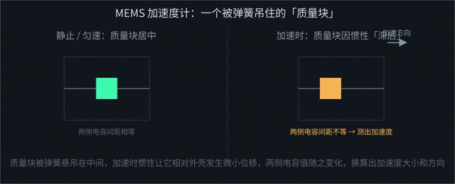
Under acceleration the proof mass lags behind the housing, the two capacitances diverge, and the difference is converted into acceleration magnitude and direction.
The figure above is a simplified illustration. In a production MEMS chip a parallel-plate capacitor has very limited sensing area and sensitivity, so the real structure is far more intricate:

Real structure: hundreds of comb-finger electrodes extend from both sides of the proof mass and interleave with the fixed fingers, building far more total capacitance in the same small area.
Viewed from above, the edge of the proof mass extends many fine “comb teeth” that interleave with teeth fixed to the chip substrate. Every interleaved pair forms a micro capacitor, and dozens to hundreds of these pairs in parallel “pool” a total capacitance change far larger than a single parallel-plate capacitor could produce in the same tiny area. That is the process detail that lets MEMS sensors be both small and sensitive, and the same design idea appears in the vibrating structure of a gyroscope. Put simply: an accelerometer does not measure “speed” but “how hard you are being pushed” — being still and moving in a straight line at constant velocity look identical to it.
The Gyroscope: Turning Rotation Into Vibration With the Coriolis Effect
A MEMS gyroscope is more ingenious than an accelerometer, and it rests on one physical phenomenon: the Coriolis effect — a vibrating object that is also rotating has its vibration direction “bent” by an extra component perpendicular to the original vibration, and the size of that component is exactly proportional to the angular velocity of the rotation.
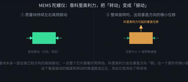
The proof mass vibrates continuously at high frequency in a known direction; once the whole device rotates, the Coriolis force bends out an extra vibration perpendicular to it, proportional to angular velocity.
Inside a MEMS gyroscope a proof mass is driven continuously along a fixed direction at high frequency — both the direction and amplitude of that drive vibration are known. Once the chip rotates with its housing, the Coriolis force superimposes a new, tiny vibration in the perpendicular direction. Measure the amplitude of that perpendicular vibration and you have measured the angular velocity of the rotation. This is why a gyroscope measures “how fast you are turning (angular rate)” rather than “how far you have turned (angle)” — the angle only appears after you integrate angular rate over time.
What Does 9-Axis Mean? Adding a Magnetometer
An accelerometer and a gyroscope each cover three axes (X/Y/Z), and together they make up what is commonly called a 6-axis IMU. Many products add a magnetometer, also on three axes, for a 9-axis unit. Why is it needed? Both the accelerometer and the gyroscope measure relative information — how much the state has changed since the previous instant — and that error inevitably accumulates over time. A magnetometer senses the absolute direction of Earth’s magnetic field, effectively a built-in compass, giving attitude estimation an absolute reference that never drifts, and it exists specifically to correct the gyroscope’s heading error.
It senses the magnetic field through the Hall effect: when a current-carrying conductive sheet is placed in a magnetic field, the charge carriers are deflected by the Lorentz force and a small voltage proportional to the field strength appears across the sheet. Put one Hall device on each of three axes and you can measure the components of Earth’s field along X/Y/Z, then derive the device’s absolute orientation relative to magnetic north. Note that a magnetometer is easily disturbed by nearby ferromagnetic objects or strong currents — metal desks, motors, speaker magnets — so in practice it usually needs a “figure-eight calibration” first, rotating the device through a three-dimensional figure-eight path so the algorithm can identify and subtract the local magnetic interference.
Gyroscope Drift: Why the Error Keeps Piling Up
Every measurement a gyroscope takes carries a small unavoidable error, and the angle is obtained by continuously integrating angular rate over time. Integration means errors add up and compound: the longer you run, the further the estimated angle drifts from the true angle — that is drift.
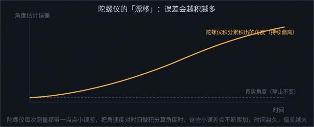
This is why a device relying on a gyroscope alone slowly loses its sense of direction — even sitting perfectly still, the integrated angle quietly wanders away. Staying accurate over the long term requires other information sources to periodically pull it back onto the correct track, which is precisely the problem sensor fusion solves.
Sensor Fusion: Letting Each Sensor Cover the Other’s Weakness
The error characteristics of an accelerometer and a gyroscope are neatly complementary. An accelerometer is easily disturbed in the short term by vibration and external shocks, and its noise is relatively high, but it does not drift persistently the way a gyroscope does. A gyroscope is fast and accurate in the short term, but accumulates an obvious bias over time.
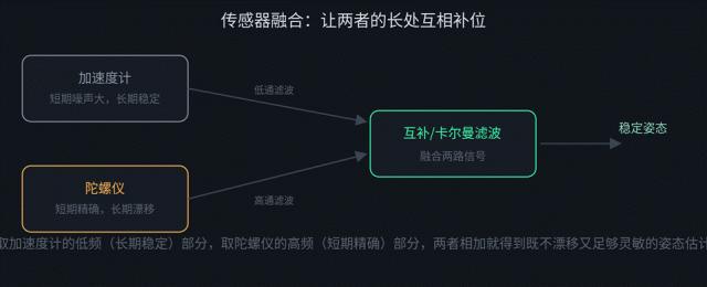
Take the accelerometer’s low-frequency (long-term stable) content and the gyroscope’s high-frequency (short-term accurate) content; the fused result is both responsive and drift-free.
The simplest fusion method is the complementary filter: pass the accelerometer data through a low-pass filter (trusting only its slow, long-term component), pass the gyroscope data through a high-pass filter (trusting only its fast, short-term component), and add the two paths together. The result is an attitude estimate that responds quickly and does not drift over the long term. A more refined approach is the Kalman filter, which continuously estimates how trustworthy each sensor currently is and adjusts the fusion weights dynamically — more accurate than a complementary filter with fixed parameters, and the most widely used fusion scheme in industry today. The “attitude awareness” in phones, drones and AR/VR headsets is this family of algorithms running in real time.
Attitude Filtering: Why You Should Never Low-Pass Euler Angles
Low-pass filtering the quaternion is far better than filtering Euler angles directly. Attitude angles are not entirely unfilterable — what is strictly forbidden is low-pass filtering the solved Euler angles on their own. The optimal engineering approach is to low-pass filter in quaternion space and only then convert to Euler angles.
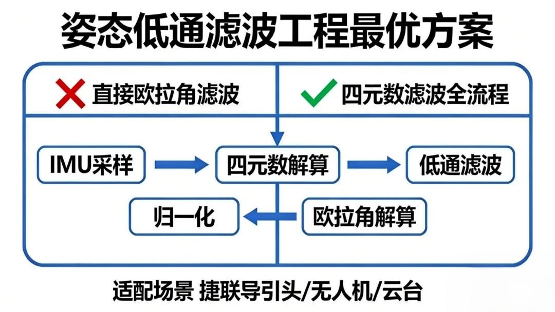
In some special cases attitude filtering really is necessary. So how should you filter attitude? You might think it is just a matter of adding a low-pass to roll, pitch and heading separately. No, no, no.
1) Gimbal Lock: The Nightmare of Attitude Filtering
Whether you use a 3-2-1 or a 2-3-1 rotation sequence, there is a step you cannot skip: the gimbal-lock singularity. Take the 2-3-1 sequence — at a pitch angle of ±90° the heading and roll axes couple, filtering amplifies the angle jumps and distorts the attitude, and the representation can no longer describe all attitudes. You might argue that if your attitude is stable and manoeuvres are gentle, and you never cross 90°, there is no gimbal lock and you can filter Euler angles after all. That is thinking too simply.
2) The 360° Wraparound: An Invisible Trap
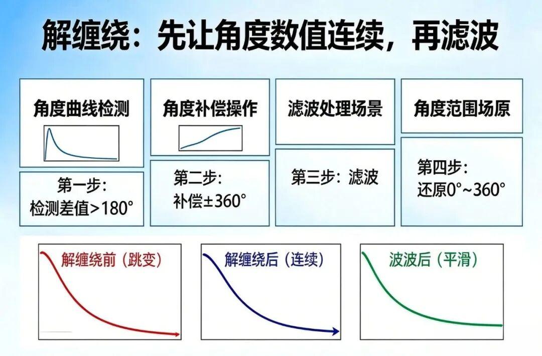
Euler angle filtering also suffers from wraparound across 360°, most visibly on periodic angles such as heading. Euler angles are periodic (0° to 360°, or ±180°), so when the angle jumps from 359° to 0° — or from 0° to 359° — there is a numerical step of 359°. The whole premise of a low-pass filter is to smooth continuous signal changes, so it misreads that step as violent noise or a sudden motion and forcibly smooths it, producing an anomalous filtered angle. If you insist on filtering Euler angles directly, and you are not worried about computational complexity or gimbal lock, then you must first “unwrap” the angle:
- Detect the angle jump (for example, where the difference between the current and previous angle exceeds 180°).
- Compensate the angle (add or subtract 360° at the jump so the values stay continuous) and record the compensation amount.
- Apply the filter.
- Convert back to the 0°–360° range.
3) Euler Angle Component Coupling
The three Euler axes are not independent of one another — they have an inherent rotation order. Filtering roll, pitch and heading separately breaks the rigid-body constraint that ties the attitude together, producing angles that look smooth but do not correspond to real motion, and solving deviations blow up for no apparent reason. For attitude filtering, pick quaternions and stop fighting with Euler angles.
How to Represent Attitude: Three Angles Eventually Lock Up
Once the fusion algorithm has computed an attitude, how should that attitude actually be represented in a computer? The most intuitive way is three angles — pitch, roll and yaw (Euler angles) — turning like three nested gimbals, one inside the next. But this representation carries a classic mathematical trap: when one layer reaches exactly 90°, two rotation axes coincide and a degree of freedom is lost — gimbal lock.
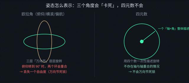
Euler angles suffer gimbal lock and lose a degree of freedom at particular angles; quaternions do not.
The industry’s standard answer is to switch to quaternions, which pack “which axis, and how far around it” into four numbers and describe the whole rotation at once. Mathematically there is no case where two axes coincide and a degree of freedom disappears, and interpolation is smoother. The cost is that quaternions are less intuitive than Euler angles: four abstract numbers do not read at a glance the way “pitch 30°, roll 10°” does. So many products run the actual computation on quaternions underneath and convert to Euler angles only when displaying the result to the user.
How Much Can Gyroscope Accuracy Differ? IMU Grades Compared
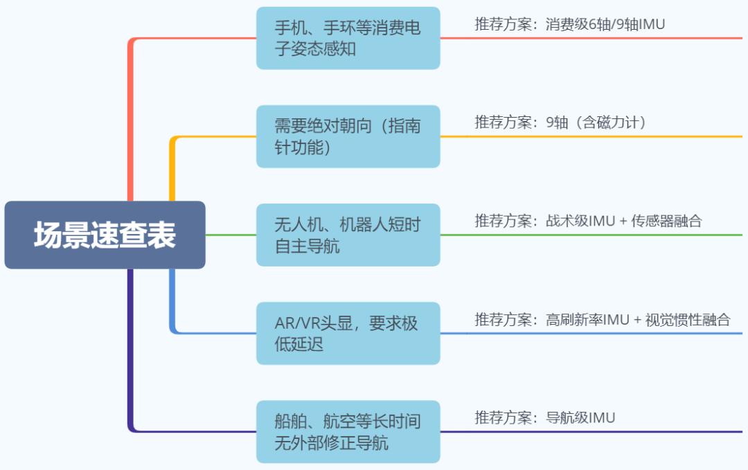
The accuracy spread across IMUs is enormous. The industry usually grades them by bias stability — how quickly a gyroscope’s output drifts while stationary:
| Grade | Typical use | Drift / bias stability | Cost |
|---|---|---|---|
| Consumer | Phones, wristbands | Fast drift; relies on frequent GPS or vision corrections | Lowest |
| Tactical | Drones, robots | Much slower drift; can carry accurate attitude and position briefly without external aid | Moderate |
| Navigation | Ships, aviation inertial navigation | Extremely high accuracy held independently for long periods, with no external correction at all | Tens of thousands of dollars |
A consumer-grade IMU is the cheapest but drifts quickly — tolerable because phones and wearables can lean on GPS and vision to re-correct constantly and never need to hold accuracy independently for long. A tactical-grade IMU drifts far more slowly and can carry reasonably accurate attitude and position estimation on its own for a short period, such as a tunnel where the GPS signal briefly disappears. A navigation-grade IMU costs tens of thousands of dollars and must hold extremely high accuracy independently for long periods with no external correction at all. That is why two parts both called “gyroscopes” can differ in price by several orders of magnitude.
Real-World Applications of IMU Sensors
The IMU is close to a standard-fit sensor in modern electronics, and its applications are broad:
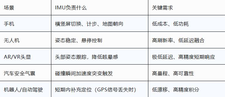
Phones and wearables use it for screen rotation, step counting and map heading, where low power and low cost dominate. Drones use it for attitude stabilisation and hover control, where high-frequency response and low-latency fusion matter most. AR/VR headsets track head pose and reduce motion sickness, demanding low latency and high short-term accuracy. Airbag systems trigger on impact and need high range and high reliability. Robots and autonomous driving lean on the IMU to bridge short GNSS outages, which calls for low drift and accurate integration.
Have questions about this article? Feel free to contact us at [email protected] — we’re happy to help!
Frequently Asked Questions
What is the difference between an accelerometer and a gyroscope?
An accelerometer measures linear acceleration on three axes; a gyroscope measures angular velocity on three axes. An accelerometer cannot tell “still” from “moving at constant velocity”, while a gyroscope cannot tell how far you have turned without integrating its rate over time. IMUs pair them because their errors are complementary.
Why does a gyroscope drift over time?
Because the angle is produced by integrating angular rate, and every measurement carries a small error. Integration accumulates those errors, so the estimated angle diverges further from the truth the longer the sensor runs. A magnetometer or another absolute reference is needed to pull the estimate back.
Why should you filter a quaternion instead of Euler angles?
Euler angles suffer gimbal lock, jump by 359° when crossing 360°, and couple across axes, all of which break a low-pass filter. Filtering the quaternion first and converting to Euler angles afterwards preserves the rigid-body constraint and avoids singularities.
What is 9-axis IMU and when do you need one?
A 9-axis IMU combines a 3-axis accelerometer, a 3-axis gyroscope and a 3-axis magnetometer. The magnetometer adds an absolute heading reference that does not drift, so a 9-axis unit is worth it whenever the device must hold heading over long periods without GNSS.
Why does a drone need sensor fusion at all?
No single MEMS sensor is accurate on every timescale. Fusion takes the accelerometer’s long-term stability and the gyroscope’s short-term speed, and Kalman filtering weights each by its current confidence. That is what keeps a drone level through vibration and brief GPS loss.
About Aomway
Aomway is a technology company specializing in drone and FPV equipment, publishing in-depth analyses of motor control, embedded hardware, and open-source robotics projects. With over 15 years of industry experience, Aomway covers the full spectrum from flight controllers and FPV goggles to thermal imaging cameras and long-range datalinks for the global drone community.