
Key Takeaways
- Modulation embeds low-frequency information onto a high-frequency carrier; without it there is no 4G/5G, Wi-Fi or satellite link.
- Analog modulation (AM, FM, PM) varies the carrier continuously, while digital modulation (ASK, FSK, PSK, QAM) jumps between a fixed set of discrete states.
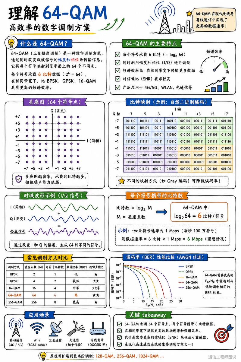
- BPSK carries 1 bit per symbol with the widest noise margin, QPSK carries 2 bits in the same bandwidth, and 64-QAM carries 6 bits — six times BPSK.
- Higher order always costs noise margin: 64 constellation points sit closer together than 2 or 4, so the same bit error rate needs a stronger signal.
- Real systems use adaptive modulation and coding (AMC), switching between BPSK and 256-QAM as channel quality rises and falls.
Digital modulation is the technique that lets a stream of 0s and 1s ride on a radio wave. It works by mapping groups of bits onto a small set of fixed states of a carrier — its amplitude, its frequency, or its phase — so that a receiver only has to decide which state it just received. Aomway walks through the whole ladder below, from the simplest two-state scheme to the dense 64-point constellation used by 4G, 5G and Wi-Fi.
What Is Modulation, and Why Does Every Wireless Link Need It?
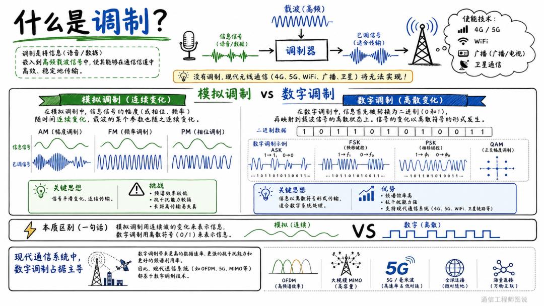
Modulation is the process of embedding a low-frequency information signal — voice, video or data — into a high-frequency carrier wave so the information can travel efficiently and reliably through a channel. Without it, 4G/5G, Wi-Fi, satellite communication and broadcast television would all be impractical: antennas scale with wavelength, and low-frequency signals cannot be radiated efficiently over long distances.
The chain is simple. An information source such as a microphone produces a baseband signal. A modulator combines that signal with a high-frequency carrier. The result is a modulated signal shaped for the transmission medium, which is then radiated by an antenna. Everything that follows in this article is a variation on one question: which property of the carrier should be changed, and how many distinct values should that property be allowed to take?
Analog vs Digital Modulation
Modulation splits into two families according to how the information is represented.
Analog modulation varies a carrier parameter smoothly and continuously, mirroring the original waveform. Amplitude modulation (AM), frequency modulation (FM) and phase modulation (PM) are the classic examples. The approach is intuitive and cheap to implement, which is why early radio, television and voice communication were built on it. Its weaknesses are equally well known: low spectral efficiency, weak immunity to additive channel noise, and progressive distortion that accumulates over long distances.
Digital modulation first converts the information into binary digits, then maps those bits onto a set of discrete carrier states. Amplitude shift keying (ASK), frequency shift keying (FSK), phase shift keying (PSK) and quadrature amplitude modulation (QAM) are the main families. Because the receiver only has to place the received signal into one of a few decision regions, small amounts of noise rarely change the outcome — and any residual errors can be cleaned up by forward error correction.
| Aspect | Analog modulation | Digital modulation |
|---|---|---|
| Information form | Continuous waveform | Discrete symbols (0/1) |
| Carrier parameter | Varies smoothly and continuously | Jumps between fixed states |
| Spectral efficiency | Low | High — rises with constellation order |
| Noise immunity | Weak; noise adds directly to the signal | Strong; the receiver decides between discrete states |
| Long-distance behaviour | Distortion accumulates and cannot be undone | Errors can be corrected with coding |
| Typical use | AM/FM broadcast, legacy TV, analog voice | 4G/5G, Wi-Fi, optical and cable broadband |
The Three Ways to Put Bits on a Carrier: ASK, FSK and PSK
Every digital scheme changes at least one property of the carrier, and the three basic families are named after exactly that property. ASK (amplitude shift keying) switches the carrier amplitude between levels. FSK (frequency shift keying) switches between two or more carrier frequencies. PSK (phase shift keying) switches the carrier phase between fixed angles.
PSK is by far the most widely deployed of the three in modern systems, and BPSK and QPSK are its two foundational forms. Both keep the carrier amplitude and frequency constant and encode information purely in phase, which is why they are relatively easy to demodulate and robust against amplitude distortion on the channel.
BPSK and QPSK: The Workhorses of Phase Modulation
BPSK: One Bit, Two Phases, Maximum Margin
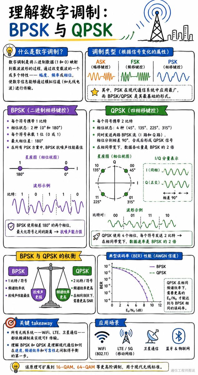
BPSK, or binary phase shift keying, is the simplest PSK scheme. Each symbol carries exactly 1 bit, represented by two phase states 180 degrees apart — conventionally 0 degrees and 180 degrees. On a constellation diagram those two points sit at opposite ends of the horizontal axis, which is the largest possible separation for two states at a given power level.
That maximum separation is why BPSK has the strongest noise immunity of any PSK scheme: a receiver can misjudge the phase only if noise pushes the signal more than 90 degrees. The trade-off is throughput — 1 bit per symbol is the lowest spectral efficiency in the PSK family. BPSK is therefore reserved for links where reliability matters more than speed, such as satellite control channels, Bluetooth low energy and many IoT radios.
QPSK: Two Bits, Four Phases, Double the Throughput
QPSK, or quadrature phase shift keying, uses four phase states — 45, 135, 225 and 315 degrees — so each symbol carries 2 bits: 00, 01, 11 and 10. In the same bandwidth, QPSK delivers twice the data throughput of BPSK.
A useful way to picture QPSK is as two BPSK streams transmitted at once on carriers 90 degrees apart, an in-phase (I) channel and a quadrature (Q) channel. The receiver separates them and recovers one bit from each. The cost of doubling the rate is that the four points are now closer together than the two BPSK points, so QPSK needs a slightly better signal-to-noise ratio than BPSK for the same error rate — a small price for double the capacity, which is why QPSK is a staple of GPS, satellite broadcasting and cellular uplinks.
64-QAM: Amplitude and Phase Together
Reading a Constellation Diagram
Unlike PSK, which only rotates the phase, QAM changes both the amplitude and the phase of the carrier. A constellation diagram plots every possible symbol as a point in the I/Q plane, so the diagram doubles as a map of the modulation’s density and of how much noise margin it has.
For 64-QAM the diagram is an 8 by 8 grid of 64 points, with I and Q amplitudes drawn from the levels plus or minus 1, 3, 5 and 7. The denser the grid, the more bits each symbol carries — and the smaller the distance between neighbouring points, which is precisely the noise margin the receiver has to work with.
Bits per Symbol
The number of bits a symbol carries is the base-2 logarithm of the number of constellation points. For 64-QAM that is log2(64) = 6 bits per symbol. The arithmetic compounds quickly: in the same bandwidth, 64-QAM moves six times the information of BPSK and three times that of QPSK. If the symbol rate is 1 Msps, the raw data rate is 6 Mbps.
QAM constellations are normally labelled so that adjacent points differ by a single bit, a technique known as Gray coding. When noise pushes a received symbol into a neighbouring decision region, only one bit is corrupted rather than several, which keeps the bit error rate far lower than the raw symbol error rate.
The Core Trade-off: Spectral Efficiency vs Noise Immunity
Every step up the modulation ladder buys speed with reliability. This is the single most important idea in the article, and it is worth stating plainly: higher-order modulation is only usable when the channel is good enough to pay for it.
| Scheme | Bits per symbol | States | Spectral efficiency | Noise margin | Typical use |
|---|---|---|---|---|---|
| BPSK | 1 | 2 phases (0, 180 deg) | Lowest | Best in the PSK family | Satellite control links, Bluetooth LE, IoT |
| QPSK | 2 | 4 phases (45, 135, 225, 315 deg) | 2x BPSK | High | GPS, satellite broadcast, cellular uplink |
| 16-QAM | 4 | 16 (4×4 grid) | 4x BPSK | Moderate | Wi-Fi at lower rates, LTE |
| 64-QAM | 6 | 64 (8×8 grid) | 6x BPSK | Lower | 4G/5G, Wi-Fi 5 and 6, cable |
| 256-QAM | 8 | 256 (16×16 grid) | 8x BPSK | Lowest | Wi-Fi 6, 5G NR near the cell centre |
Plotted as bit error rate against signal-to-noise ratio, the curves tell the same story from the receiver’s side. Under additive white Gaussian noise, BPSK and QPSK reach a low error rate at a modest SNR, while 64-QAM and 256-QAM need substantially more signal power to achieve the same reliability. The gap widens with every doubling of the constellation size.
Adaptive Modulation and Coding: Choosing the Scheme Per Millisecond
Real systems do not commit to a single scheme. They use adaptive modulation and coding (AMC), which re-selects the modulation order and the coding rate according to the current channel quality, typically on a millisecond timescale.
| Channel condition | Typical choice | Reasoning |
|---|---|---|
| Excellent SNR — user close to the base station or router | 256-QAM or 64-QAM | Spare margin is spent on throughput instead of being wasted |
| Good SNR | 16-QAM or QPSK | Balanced rate and robustness |
| Poor SNR — cell edge, heavy shadowing or interference | QPSK or BPSK | Reliability over rate, so the link does not drop |
The feedback loop is what makes modern cellular and Wi-Fi throughput so uneven in practice. A phone that reports a strong channel is scheduled with 256-QAM and a high coding rate; walk behind a wall and the scheduler drops it back to QPSK within milliseconds to keep the connection alive.
What This Means for Drones, FPV and Long-Range Links
The same trade-off governs every radio a drone carries. A long-range control or video link that has to hold at 10 km or more is generally running a low-order scheme, because the received SNR at that distance simply will not support a dense constellation. Move the aircraft closer and the link can shift to a higher order and carry far more data in the same channel — which is exactly why video quality improves sharply as you fly back toward yourself.
It also explains why a link that works perfectly on the bench can fail in the air. Multipath, antenna orientation and interference all reduce the effective SNR, and the modem responds by dropping to a more robust scheme, which means less throughput for the same bandwidth. When you evaluate a datalink, the modulation order it can hold at a given distance is a more meaningful specification than its peak headline rate. You can see the hardware Aomway builds for these links at www.aomway.com.
Have questions about this article? Feel free to contact us at [email protected] — we’re happy to help!
Frequently Asked Questions
What is the difference between analog and digital modulation?
Analog modulation varies a carrier parameter smoothly and continuously to mirror the original waveform, as in AM and FM radio. Digital modulation first converts the information into bits and then maps them onto a fixed set of discrete carrier states, so the receiver only has to decide which state it received rather than reproduce the waveform exactly.
Why does BPSK have better noise immunity than QPSK or 64-QAM?
Because its two constellation points are 180 degrees apart — the widest possible separation for two states at a given power. QPSK’s four points and 64-QAM’s 64 points sit progressively closer together, so a smaller amount of noise is enough to push a received symbol into the wrong decision region.
How many bits does one 64-QAM symbol carry?
Six. The number of bits per symbol equals the base-2 logarithm of the constellation size, and log2(64) is 6. At a symbol rate of 1 Msps, 64-QAM therefore delivers a raw 6 Mbps, six times what BPSK would achieve in the same bandwidth.
What is a constellation diagram?
It is a two-dimensional plot of every symbol a modulation scheme can transmit, with the in-phase component on one axis and the quadrature component on the other. The spacing between points shows how much noise margin the scheme has: dense constellations carry more bits per symbol but tolerate less noise.
What is adaptive modulation and coding (AMC)?
AMC is the technique modern systems use to switch modulation order and coding rate as channel quality changes. Users close to a base station get high-order schemes such as 256-QAM for maximum speed, while users at the cell edge fall back to QPSK or BPSK so the connection stays up instead of dropping.
Why do 4G and 5G use higher-order QAM only near the cell centre?
Because 64-QAM and 256-QAM need a high signal-to-noise ratio to be decoded reliably. Only users with a strong, clean channel have enough margin to support them. Everyone else is served with a lower-order scheme that trades throughput for a lower bit error rate.
About Aomway
Aomway is a technology company specializing in drone and FPV equipment, publishing in-depth analyses of radio links, embedded hardware and open-source robotics projects. With over 15 years of industry experience, Aomway covers the full spectrum from flight controllers and FPV goggles to thermal imaging cameras and long-range datalinks for the global drone community.