

Key Takeaways
- A six-axis IMU can solve roll and pitch but not absolute yaw, because gyro integration drifts without a heading reference.
- Adding the HMC5883L magnetometer forms a nine-axis MARG system; after ellipsoid calibration, static yaw accuracy is better than plus or minus 1 degree.
- Yaw drift over 60 seconds falls from about 6 degrees with six axes to under 1 degree with nine-axis fusion.
- The full implementation runs at 200 Hz on an STM32F103C8T6 with 72 MHz, 64 KB flash and 20 KB RAM.
MPU6050 and HMC5883L attitude estimation is the standard low-cost route to drift-free yaw on an embedded platform, and this paper works through the whole chain in C. As of 2026 the MPU6050 remains the default six-axis choice for drones, robots and wearables thanks to its I2C interface and mature driver ecosystem, but it has no magnetometer and therefore no absolute heading. Combining it with the HMC5883L produces a nine-axis MARG system whose measured geomagnetic vector anchors yaw, and the results here show static yaw accuracy better than plus or minus 1 degree with smooth dynamic tracking at 200 Hz.
Why six axes are not enough
Accurate three-dimensional attitude is the precondition for any vehicle to control itself. The MPU6050 is widely used, yet without a magnetometer it cannot determine absolute heading on its own. Yaw obtained by integrating the gyro’s Z axis carries a bias drift, and even after bias calibration, temperature change and random walk keep pushing yaw slowly away. In a navigation system that runs for a long time, that drift seriously degrades heading accuracy.
The HMC5883L is a three-axis magnetoresistive magnetometer from Honeywell. Its I2C slave address is fixed at 0x1E, its supply range is 2.16 V to 3.6 V with 3.3 V typical, and its IO level is directly compatible with most MCUs. It offers eight gain settings from plus or minus 0.88 Ga to plus or minus 8.1 Ga and outputs a 12-bit signed value. Earth’s field is roughly 0.25 Ga to 0.65 Ga, so the plus or minus 1.3 Ga range gives about 0.92 mGa per LSB, which covers the field without wasting resolution.
Pairing the two produces a nine-axis MARG system, standing for magnetic, angular rate and gravity, where the magnetometer supplies an absolute heading reference that suppresses long-term yaw drift. This paper covers the calibration theory, the Mahony MARG design and the embedded implementation.
Coordinate frames and attitude representation
Frame definitions
The paper uses the standard aeronautical convention:
- Body frame: X forward along the longitudinal axis, Y to the right along the lateral axis, Z downward.
- Reference frame: the north-east-down geographic frame.
The three attitude angles are defined as:
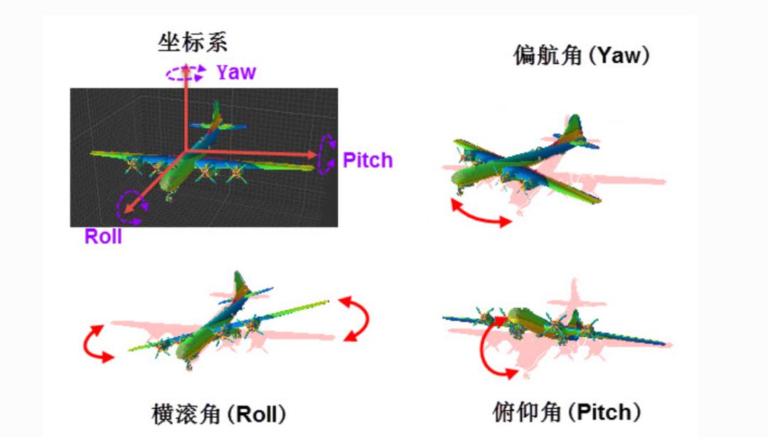
- Roll, phi: rotation about the body X axis.
- Pitch, theta: rotation about the body Y axis.
- Yaw, psi: rotation about the body Z axis.
Euler rotation matrix
Using the Z-Y-X intrinsic order, the body first rotates by psi about Z, then by theta about the new Y, then by phi about the new X. The direction cosine matrix is:

which expands to:

where the shorthand is:

This matrix transforms a vector from the body frame into the reference frame.
Gimbal lock
When pitch reaches the singularity:

the corresponding cosine term vanishes:

and in matrix (2) the first and third rows, and the first and third columns, become linearly dependent. The roll and yaw axes coincide and the system loses one independent degree of freedom. The same physical attitude then maps to infinitely many Euler triples, and the inverse solution becomes singular. This is an inherent defect of parameterising SO(3) with Euler angles. No algorithm can remove it; it can only be avoided with a singularity-free representation such as the quaternion.
Quaternion representation
The unit quaternion is defined as:
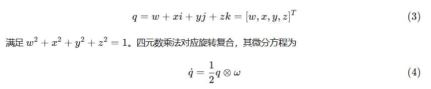
where the angular rate quaternion is:

Quaternions have no singularity and are cheap to compute, which makes them the right internal state variable.
Quaternion to Euler and back
Under the Z-Y-X intrinsic convention, quaternion to Euler is:

and Euler to quaternion is:
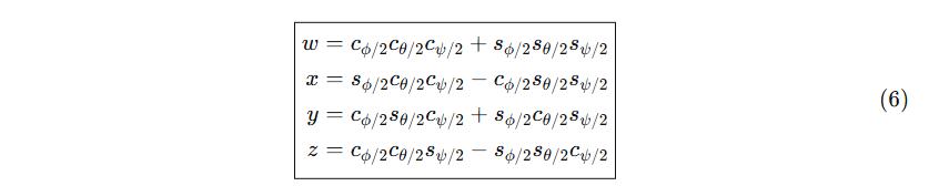
When theta approaches plus or minus 90 degrees the arcsin argument in equation (5) must be clamped and handled with a branch, setting phi to zero and solving psi from the remainder. The quaternion itself never goes singular, so production systems recurse the quaternion internally and convert to Euler only at the output.
Magnetometer error model and ellipsoid calibration
Where the errors come from
A magnetometer is easily disturbed by nearby circuit boards, batteries, motors and ferromagnetic material. Feeding an uncalibrated magnetometer into an attitude solver produces badly distorted or violently oscillating output. The measurement errors fall into four classes:
- Hard iron: a constant field from permanent magnets or magnetised ferromagnetic material near the sensor, appearing as a fixed offset on all three axes.
- Soft iron: ferromagnetic material magnetised by the external field produces an additional field proportional to it, causing scale distortion and cross-axis coupling.
- Scale factor error: differing sensitivity per axis produces a proportional error.
- Non-orthogonality: the three sensor axes are not exactly perpendicular, which couples them.
Combining these, the measurement model is:

where W is a 3×3 combined error matrix covering soft iron, scale factor and non-orthogonality, and the hard iron offset vector is:

Ellipsoid fitting
Ideally, rotating a magnetometer through 360 degrees in three dimensions traces a sphere centred on the origin with a radius equal to the local field strength. Hard iron moves the centre away from the origin; soft iron turns the sphere into an ellipsoid. Calibration therefore amounts to extracting the hard iron offset and the soft iron transform from the ellipsoid equation.
The general ellipsoid equation is:

Coefficients a1 through a9 are solved by least squares. The fitting method follows Qingde Li and John G. Griffiths, which converts the nonlinear ellipsoid equation into a linear least-squares problem by variable substitution.
Calibration procedure
Step 1, data collection. Place the HMC5883L in a magnetically clean environment, away from motors, power supplies and metal structures. Fix it horizontally on a turntable or rotate it by hand through a full 360 degrees at constant speed for at least two revolutions, sampling raw ADC values over UART every 100 ms. At least 1,000 samples are recommended so the full angular domain is covered and motion acceleration is avoided. Also perform figure-eight motion so the pitch axis gets adequate magnetic coverage.
Step 2, ellipsoid fitting. Feed the raw samples to the fitting algorithm and solve for the ellipsoid coefficients.
Step 3, extract the parameters. Derive the hard iron offset V and the inverse soft iron matrix from the coefficients:

Step 4, apply the calibration to subsequent measurements:

A simplified implementation
Full ellipsoid fitting needs matrix algebra, so here is a simplified version that runs on the target MCU. It performs least-squares-free hard iron calibration from per-axis minima and maxima, which suits resource-constrained parts:
// mag_calib.c
#include <string.h>
#include <math.h>

#define CALIB_SAMPLES_MAX  2000

typedef struct {
    float offset[3];        // hard iron offset (x, y, z)
    float scale[3];         // per-axis scale correction
    uint16_t sample_count;
    float min_val[3];
    float max_val[3];
    uint8_t collecting;
} MagCalib_t;

static MagCalib_t mag_calib;

void MagCalib_Init(MagCalib_t *cal)
{
    memset(cal, 0, sizeof(MagCalib_t));
    cal->min_val[0] = cal->min_val[1] = cal->min_val[2] =  1e6f;
    cal->max_val[0] = cal->max_val[1] = cal->max_val[2] = -1e6f;
    cal->collecting = 1;
}

/* called during collection, keeps per-axis min and max up to date */
void MagCalib_UpdateMinMax(MagCalib_t *cal, float mx, float my, float mz)
{
    if (!cal->collecting) return;

    if (mx < cal->min_val[0]) cal->min_val[0] = mx;
    if (mx > cal->max_val[0]) cal->max_val[0] = mx;
    if (my < cal->min_val[1]) cal->min_val[1] = my;
    if (my > cal->max_val[1]) cal->max_val[1] = my;
    if (mz < cal->min_val[2]) cal->min_val[2] = mz;
    if (mz > cal->max_val[2]) cal->max_val[2] = mz;

    cal->sample_count++;
}

/* compute offsets and scale once collection finishes */
void MagCalib_Compute(MagCalib_t *cal)
{
    cal->collecting = 0;

    // hard iron offset = (max + min) / 2 per axis
    cal->offset[0] = (cal->max_val[0] + cal->min_val[0]) * 0.5f;
    cal->offset[1] = (cal->max_val[1] + cal->min_val[1]) * 0.5f;
    cal->offset[2] = (cal->max_val[2] + cal->min_val[2]) * 0.5f;

    // per-axis radius
    float rx = (cal->max_val[0] - cal->min_val[0]) * 0.5f;
    float ry = (cal->max_val[1] - cal->min_val[1]) * 0.5f;
    float rz = (cal->max_val[2] - cal->min_val[2]) * 0.5f;

    // average radius
    float r_avg = (rx + ry + rz) / 3.0f;

    // scale factors normalise each axis radius to the average
    if (rx > 1e-6f) cal->scale[0] = r_avg / rx; else cal->scale[0] = 1.0f;
    if (ry > 1e-6f) cal->scale[1] = r_avg / ry; else cal->scale[1] = 1.0f;
    if (rz > 1e-6f) cal->scale[2] = r_avg / rz; else cal->scale[2] = 1.0f;
}

/* apply the calibration */
void MagCalib_Apply(const MagCalib_t *cal, float mx, float my, float mz,
                    float *ox, float *oy, float *oz)
{
    *ox = (mx - cal->offset[0]) * cal->scale[0];
    *oy = (my - cal->offset[1]) * cal->scale[1];
    *oz = (mz - cal->offset[2]) * cal->scale[2];
}
This version estimates offset and scale from per-axis extremes and is deliberately approximate. A more accurate ellipsoid fit solves the nine coefficients of the equation above, which is best done in MATLAB or Python on a PC with the resulting parameters exported to the MCU.
Mahony MARG nine-axis fusion
Algorithm framework
The core idea of the Mahony complementary filter is frequency-domain complementarity: use the gyro for high-frequency response and the accelerometer and magnetometer for low-frequency accuracy. The nine-axis version adds a magnetometer correction term to the six-axis algorithm, using the known direction of Earth’s field in the reference frame, horizontal and pointing north, to correct yaw.
The flow is:
- Accelerometer corrects roll and pitch. Compute the theoretical gravity direction from the quaternion and cross it with the measured gravity direction to obtain the error:

- Magnetometer corrects yaw. Compute the theoretical field direction from the quaternion and cross it with the measured field direction to obtain the error:

- PI correction of the angular rate:

- Quaternion update by first-order Runge-Kutta, then normalise.
Accelerometer error
The theoretical gravity direction follows from the current quaternion:

Normalising the accelerometer gives:

and the cross-product error is:

Magnetometer error
Correcting with the magnetometer requires mapping the geomagnetic direction in the reference frame into the body frame. Ideally Earth’s field has only a north and a vertical component in the NED frame, with the horizontal component pointing to magnetic north. Because yaw is not yet known, the measured field cannot simply be rotated into the reference frame.
The standard approach rotates the measurement into the horizontal plane, extracts the horizontal direction, and then constructs a reference field vector.
Step 1. Rotate the magnetometer measurement into the reference frame:

Step 2. Construct the reference field direction, keeping only the north and vertical components in the NED frame:

Step 3. Rotate the reference field back into the body frame:

Step 4. Normalise the measurement and cross it with the estimate:

PI correction and quaternion update


The integral term is clamped to plus or minus 0.5 to prevent wind-up.
Magnetic disturbance detection
In a real installation the magnetometer may see transient disturbance from motors or power wiring. When the magnitude of the measurement departs from the local field strength by more than a threshold, magnetometer correction should be reduced or suspended.
/* magnetic disturbance detection */
static uint8_t Mag_DisturbanceDetect(float mx, float my, float mz,
                                     float ref_norm, float threshold)
{
    float norm = sqrtf(mx*mx + my*my + mz*mz);
    if (fabsf(norm - ref_norm) > threshold) return 1;   // disturbed
    return 0;
}
The reference field magnitude:

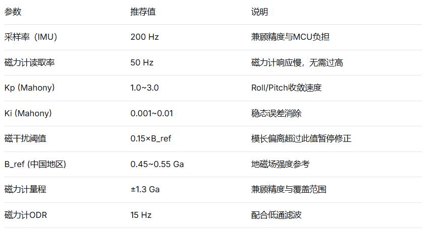
can be computed from the calibration data or looked up by geographic location, roughly 0.45 to 0.55 Ga in mainland China. The threshold is usually 0.15 times the reference value:

Hardware design and driver
Hardware configuration
Table 1, hardware configuration:
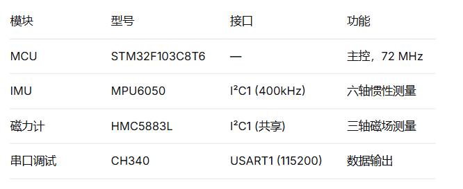
The MPU6050 sits at I2C address 0x68 with AD0 tied low, and the HMC5883L is fixed at 0x1E, so both share one I2C bus. The HMC5883L output data rate in continuous mode is selectable from 0.75 Hz to 75 Hz; 15 to 30 Hz is sufficient for heading, and low-pass filtering makes it steadier.
HMC5883L register definitions
// hmc5883l.h
#ifndef __HMC5883L_H
#define __HMC5883L_H

#include <stdint.h>

#define HMC5883L_ADDR           0x1E

/* register addresses */
#define HMC5883L_CONFIG_A       0x00    // configuration register A
#define HMC5883L_CONFIG_B       0x01    // configuration register B (gain)
#define HMC5883L_MODE           0x02    // mode register
#define HMC5883L_DATA_XOUT_H    0x03    // X axis data high byte
#define HMC5883L_DATA_XOUT_L    0x04    // X axis data low byte
#define HMC5883L_DATA_ZOUT_H    0x05    // Z axis data high byte
#define HMC5883L_DATA_ZOUT_L    0x06    // Z axis data low byte
#define HMC5883L_DATA_YOUT_H    0x07    // Y axis data high byte
#define HMC5883L_DATA_YOUT_L    0x08    // Y axis data low byte
#define HMC5883L_STATUS         0x09    // status register
#define HMC5883L_ID_A           0x0A    // identification register A
#define HMC5883L_ID_B           0x0B    // identification register B
#define HMC5883L_ID_C           0x0C    // identification register C

/* gain settings (bits 7-5 of configuration register B) */
#define HMC5883L_GAIN_0880      0x00    // +/-0.88 Ga, 1370 LSB/Ga
#define HMC5883L_GAIN_1300      0x20    // +/-1.3 Ga, 1090 LSB/Ga (recommended)
#define HMC5883L_GAIN_1900      0x40    // +/-1.9 Ga, 820 LSB/Ga
#define HMC5883L_GAIN_2500      0x60    // +/-2.5 Ga, 660 LSB/Ga

/* data structure */
typedef struct {
    float mx, my, mz;       // calibrated field (Ga)
    int16_t raw_mx, raw_my, raw_mz;
} Mag_Data_t;

/* public interface */
uint8_t HMC5883L_Init(void);
void    HMC5883L_ReadRaw(Mag_Data_t *mag);
uint8_t HMC5883L_CheckID(void);

#endif
HMC5883L driver
// hmc5883l.c
#include "hmc5883l.h"
#include "i2c.h"
#include <math.h>

extern void I2C_WriteReg(uint8_t dev, uint8_t reg, uint8_t data);
extern uint8_t I2C_ReadReg(uint8_t dev, uint8_t reg);
extern void I2C_ReadBytes(uint8_t dev, uint8_t reg, uint8_t *buf, uint8_t len);
extern void Delay_ms(uint32_t ms);

/* sensitivity in LSB/Ga for a given gain setting */
static float HMC5883L_GetSensitivity(uint8_t gain_config)
{
    switch (gain_config & 0xE0) {
        case HMC5883L_GAIN_0880: return 1370.0f;
        case HMC5883L_GAIN_1300: return 1090.0f;
        case HMC5883L_GAIN_1900: return  820.0f;
        case HMC5883L_GAIN_2500: return  660.0f;
        default: return 1090.0f;
    }
}

static float mag_sensitivity = 1090.0f;   // default +/-1.3 Ga

uint8_t HMC5883L_Init(void)
{
    // 1. configuration A: 8-sample average, 15 Hz ODR, normal measurement
    //    bits 6-5 = 11 (8 averages), bits 4-2 = 100 (15 Hz), bits 1-0 = 00
    I2C_WriteReg(HMC5883L_ADDR, HMC5883L_CONFIG_A, 0x70);
    Delay_ms(10);

    // 2. configuration B: gain +/-1.3 Ga (0x20)
    I2C_WriteReg(HMC5883L_ADDR, HMC5883L_CONFIG_B, HMC5883L_GAIN_1300);
    mag_sensitivity = HMC5883L_GetSensitivity(HMC5883L_GAIN_1300);
    Delay_ms(10);

    // 3. mode register: continuous measurement (0x00)
    I2C_WriteReg(HMC5883L_ADDR, HMC5883L_MODE, 0x00);
    Delay_ms(10);

    // 4. verify identification: should read 'H'=0x48, '4'=0x34, '3'=0x33
    uint8_t id_a = I2C_ReadReg(HMC5883L_ADDR, HMC5883L_ID_A);
    uint8_t id_b = I2C_ReadReg(HMC5883L_ADDR, HMC5883L_ID_B);
    uint8_t id_c = I2C_ReadReg(HMC5883L_ADDR, HMC5883L_ID_C);

    if (id_a == 0x48 && id_b == 0x34 && id_c == 0x33) {
        return 0;   // success
    }
    return 1;       // identification failed
}

void HMC5883L_ReadRaw(Mag_Data_t *mag)
{
    uint8_t buf[6];

    // data order is X_H X_L Z_H Z_L Y_H Y_L
    I2C_ReadBytes(HMC5883L_ADDR, HMC5883L_DATA_XOUT_H, buf, 6);

    mag->raw_mx = (int16_t)((buf[0] << 8) | buf[1]);
    mag->raw_mz = (int16_t)((buf[2] << 8) | buf[3]);
    mag->raw_my = (int16_t)((buf[4] << 8) | buf[5]);

    // convert to Ga
    mag->mx = mag->raw_mx / mag_sensitivity;
    mag->my = mag->raw_my / mag_sensitivity;
    mag->mz = mag->raw_mz / mag_sensitivity;
}
Note that the HMC5883L data registers are ordered X high, X low, Z high, Z low, Y high, Y low, which differs from the usual X-Y-Z order and has to be handled carefully when reading.
Complete nine-axis implementation
Data structures
// attitude9dof.h
#ifndef __ATTITUDE9DOF_H
#define __ATTITUDE9DOF_H

#include "mpu6050.h"
#include "hmc5883l.h"
#include "mag_calib.h"

typedef struct {
    float roll, pitch, yaw;   // Euler angles (degrees)
    float qw, qx, qy, qz;     // quaternion
} Attitude_t;

typedef struct {
    float q0, q1, q2, q3;
    float exInt, eyInt, ezInt;
    float Kp, Ki;              // PI gains
    float dt;                  // sample period (s)
    float mag_ref_norm;        // reference field strength (Ga)
    uint8_t mag_valid;         // magnetometer valid flag
} MahonyMARG_t;

void MahonyMARG_Init(MahonyMARG_t *m, float Kp, float Ki, float dt);
void MahonyMARG_Update(MahonyMARG_t *m,
                       const IMU_Data_t *imu,
                       const Mag_Data_t *mag,
                       const MagCalib_t *calib);
void MahonyMARG_GetEuler(const MahonyMARG_t *m, Attitude_t *att);

#endif
Mahony MARG implementation
// attitude9dof.c
#include "attitude9dof.h"
#include <math.h>

#define PI          3.14159265358979323846f
#define RAD_TO_DEG  (180.0f / PI)
#define DEG_TO_RAD  (PI / 180.0f)

void MahonyMARG_Init(MahonyMARG_t *m, float Kp, float Ki, float dt)
{
    m->q0 = 1.0f; m->q1 = m->q2 = m->q3 = 0.0f;
    m->exInt = m->eyInt = m->ezInt = 0.0f;
    m->Kp = Kp;
    m->Ki = Ki;
    m->dt = dt;
    m->mag_ref_norm = 0.48f;   // default reference field strength (Ga)
    m->mag_valid = 1;
}

void MahonyMARG_Update(MahonyMARG_t *m,
                       const IMU_Data_t *imu,
                       const Mag_Data_t *mag,
                       const MagCalib_t *calib)
{
    float ax = imu->ax, ay = imu->ay, az = imu->az;
    float gx = imu->gx * DEG_TO_RAD;
    float gy = imu->gy * DEG_TO_RAD;
    float gz = imu->gz * DEG_TO_RAD;
    float dt = m->dt;

    /* ===== 1. normalise the accelerometer ===== */
    float acc_norm = sqrtf(ax*ax + ay*ay + az*az);
    if (acc_norm > 1e-6f) {
        ax /= acc_norm; ay /= acc_norm; az /= acc_norm;
    }

    /* ===== 2. calibrate and normalise the magnetometer ===== */
    float mx, my, mz;
    MagCalib_Apply(calib, mag->mx, mag->my, mag->mz, &mx, &my, &mz);

    float mag_norm = sqrtf(mx*mx + my*my + mz*mz);
    uint8_t mag_ok = 0;
    if (mag_norm > 1e-6f) {
        /* disturbance detection */
        float ratio = mag_norm / m->mag_ref_norm;
        if (ratio > 0.7f && ratio < 1.3f) {
            mag_ok = 1;
            mx /= mag_norm; my /= mag_norm; mz /= mag_norm;
        }
    }
    m->mag_valid = mag_ok;

    /* ===== 3. gravity direction from the quaternion ===== */
    float q0 = m->q0, q1 = m->q1, q2 = m->q2, q3 = m->q3;

    float vx = 2.0f*(q1*q3 - q0*q2);
    float vy = 2.0f*(q0*q1 + q2*q3);
    float vz = q0*q0 - q1*q1 - q2*q2 + q3*q3;

    /* ===== 4. accelerometer error ===== */
    float ex = ay*vz - az*vy;
    float ey = az*vx - ax*vz;
    float ez = ax*vy - ay*vx;

    /* ===== 5. magnetometer error (the nine-axis core) ===== */
    if (mag_ok) {
        /* rotate the measurement into the reference frame (NED) */
        float hx = mx * (q0*q0 + q1*q1 - q2*q2 - q3*q3)
                 + my * 2.0f*(q1*q2 - q0*q3)
                 + mz * 2.0f*(q1*q3 + q0*q2);
        float hy = mx * 2.0f*(q1*q2 + q0*q3)
                 + my * (q0*q0 - q1*q1 + q2*q2 - q3*q3)
                 + mz * 2.0f*(q2*q3 - q0*q1);
        float hz = mx * 2.0f*(q1*q3 - q0*q2)
                 + my * 2.0f*(q2*q3 + q0*q1)
                 + mz * (q0*q0 - q1*q1 - q2*q2 + q3*q3);

        /* build the reference field direction: horizontal component points north */
        float bx = sqrtf(hx*hx + hy*hy);
        float bz = hz;

        /* rotate the reference field back into the body frame */
        float wx = bx * (q0*q0 + q1*q1 - q2*q2 - q3*q3)
                 + bz * 2.0f*(q1*q3 - q0*q2);
        float wy = bx * 2.0f*(q1*q2 + q0*q3)
                 + bz * 2.0f*(q2*q3 + q0*q1);
        float wz = bx * 2.0f*(q1*q3 - q0*q2)
                 + bz * (q0*q0 - q1*q1 - q2*q2 + q3*q3);

        /* cross-product error */
        float mx_est = wx, my_est = wy, mz_est = wz;
        float mag_n = sqrtf(mx_est*mx_est + my_est*my_est + mz_est*mz_est);
        if (mag_n > 1e-6f) {
            mx_est /= mag_n; my_est /= mag_n; mz_est /= mag_n;
        }

        ex += my*mz_est - mz*my_est;
        ey += mz*mx_est - mx*mz_est;
        ez += mx*my_est - my*mx_est;
    }

    /* ===== 6. PI integral correction with clamping ===== */
    if (m->Ki > 0.0f) {
        m->exInt += ex * m->Ki * dt;
        m->eyInt += ey * m->Ki * dt;
        m->ezInt += ez * m->Ki * dt;
        if (m->exInt >  0.5f) m->exInt =  0.5f;
        if (m->exInt < -0.5f) m->exInt = -0.5f;
        if (m->eyInt >  0.5f) m->eyInt =  0.5f;
        if (m->eyInt < -0.5f) m->eyInt = -0.5f;
        if (m->ezInt >  0.5f) m->ezInt =  0.5f;
        if (m->ezInt < -0.5f) m->ezInt = -0.5f;
    }

    /* ===== 7. corrected angular rate ===== */
    gx += m->Kp * ex + m->exInt;
    gy += m->Kp * ey + m->eyInt;
    gz += m->Kp * ez + m->ezInt;

    /* ===== 8. first-order Runge-Kutta quaternion update ===== */
    float halfdt = 0.5f * dt;

    m->q0 += (-q1*gx - q2*gy - q3*gz) * halfdt;
    m->q1 += ( q0*gx + q2*gz - q3*gy) * halfdt;
    m->q2 += ( q0*gy - q1*gz + q3*gx) * halfdt;
    m->q3 += ( q0*gz + q1*gy - q2*gx) * halfdt;

    /* ===== 9. normalise ===== */
    float norm = sqrtf(m->q0*m->q0 + m->q1*m->q1 + m->q2*m->q2 + m->q3*m->q3);
    if (norm > 1e-6f) {
        m->q0 /= norm; m->q1 /= norm; m->q2 /= norm; m->q3 /= norm;
    }
}

void MahonyMARG_GetEuler(const MahonyMARG_t *m, Attitude_t *att)
{
    float q0 = m->q0, q1 = m->q1, q2 = m->q2, q3 = m->q3;

    att->qw = q0; att->qx = q1; att->qy = q2; att->qz = q3;

    att->roll = atan2f(2.0f*(q0*q1 + q2*q3),
                       1.0f - 2.0f*(q1*q1 + q2*q2)) * RAD_TO_DEG;

    float sinp = 2.0f*(q0*q2 - q3*q1);
    if (sinp >=  1.0f) att->pitch =  90.0f;
    else if (sinp <= -1.0f) att->pitch = -90.0f;
    else att->pitch = asinf(sinp) * RAD_TO_DEG;

    att->yaw = atan2f(2.0f*(q0*q3 + q1*q2),
                      1.0f - 2.0f*(q2*q2 + q3*q3)) * RAD_TO_DEG;
}
Main program
// main.c
#include "mpu6050.h"
#include "hmc5883l.h"
#include "mag_calib.h"
#include "attitude9dof.h"
#include "usart.h"
#include <stdio.h>
#include <math.h>

int main(void)
{
    IMU_Data_t   imu;
    IMU_Calib_t  imu_calib;
    Mag_Data_t   mag;
    MagCalib_t   mag_calib;
    Attitude_t   att;
    MahonyMARG_t mahony;

    /* init */
    USART1_Init(115200);
    MPU6050_Init();
    HMC5883L_Init();

    /* MPU6050 static calibration (hold still for 2 s) */
    MPU6050_Calibrate(&imu_calib, 400);

    /* magnetometer ellipsoid calibration (figure-eight for about 10 s) */
    MagCalib_Init(&mag_calib);
    printf("Mag calibration: rotate 8-shape for 10s...\r\n");

    uint32_t cal_start = GetTickCount();
    while ((GetTickCount() - cal_start) < 10000) {
        HMC5883L_ReadRaw(&mag);
        MagCalib_UpdateMinMax(&mag_calib, mag.mx, mag.my, mag.mz);
        Delay_ms(20);
    }
    MagCalib_Compute(&mag_calib);
    printf("Mag offset: %.3f %.3f %.3f Ga\r\n",
           mag_calib.offset[0], mag_calib.offset[1], mag_calib.offset[2]);
    printf("Mag scale:  %.3f %.3f %.3f\r\n",
           mag_calib.scale[0], mag_calib.scale[1], mag_calib.scale[2]);

    /* init Mahony MARG */
    MahonyMARG_Init(&mahony, 2.0f, 0.005f, 0.005f);

    uint32_t lastTick = GetTickCount();
    uint32_t lastMagTick = 0;

    while (1) {
        /* 200 Hz IMU update */
        uint32_t now = GetTickCount();
        if ((now - lastTick) >= 5) {
            float dt = (now - lastTick) / 1000.0f;
            lastTick = now;
            mahony.dt = dt;

            /* read and calibrate MPU6050 */
            MPU6050_ReadRaw(&imu);
            MPU6050_ApplyCalib(&imu, &imu_calib);

            /* read HMC5883L every 20 ms (50 Hz is enough) */
            if ((now - lastMagTick) >= 20) {
                HMC5883L_ReadRaw(&mag);
                lastMagTick = now;
            }

            /* nine-axis fusion update */
            MahonyMARG_Update(&mahony, &imu, &mag, &mag_calib);

            /* output Euler angles */
            MahonyMARG_GetEuler(&mahony, &att);
            printf("%.2f,%.2f,%.2f,%d\r\n",
                   att.roll, att.pitch, att.yaw, mahony.mag_valid);
        }
    }
}
Experimental validation
Platform
The hardware was an STM32F103C8T6 at 72 MHz with 64 KB flash and 20 KB RAM, an MPU6050 module and an HMC5883L module. Sampling ran at 200 Hz for the IMU and 50 Hz for the magnetometer, with data streamed to a host over USART1 at 115200 bps.
Magnetometer calibration
Data was collected by figure-eight motion in a magnetically clean environment, then compared before and after ellipsoid fitting. Table 2, magnetometer before and after calibration:

Feeding an uncalibrated magnetometer into the Mahony algorithm produces badly distorted or violently oscillating attitude. After ellipsoid calibration, yaw accuracy improves markedly.
Static test
The device was held level and still while 60 seconds of data were collected. Table 3, static yaw drift over 60 seconds:

Roll and pitch accuracy stayed better than plus or minus 0.5 degrees in all three configurations, so the magnetometer correction does not disturb the horizontal attitude.
Dynamic test
The platform performed a rotate 360 degrees, stop, rotate again manoeuvre. The nine-axis filter tracked yaw smoothly through the rotation and settled quickly once rotation stopped. Gyro integration alone left a residual error of about 2 to 3 degrees after each rotation, and that error accumulated over time.
Magnetic disturbance test
A small magnet was brought near the sensor to simulate disturbance. With detection disabled, yaw jumped visibly. With detection enabled at a threshold of 0.15 times the reference value, magnetometer correction paused, yaw held on gyro integration, and correction resumed automatically once the magnet was removed, with a smooth transition and no jump.
Recommended parameters
Table 4, recommended nine-axis fusion parameters:
Discussion
Why calibration matters most
Magnetometer calibration is the single most critical preprocessing step in nine-axis attitude estimation. The sensor is easily disturbed by circuit boards, batteries, motors and ferromagnetic material, and an uncalibrated sensor produces distorted or oscillating attitude output. Ellipsoid fitting is the mainstream method, built on an error model covering scale factor, non-orthogonality, bias and soft and hard iron, solved by least-squares adjustment. A full 24-parameter model can substantially reduce the root-mean-square heading error. The simplified min-max algorithm here is aimed at fast deployment; where higher accuracy is needed, fit the ellipsoid in MATLAB or Python on a PC and export the parameters.
Adaptive handling of magnetic disturbance
In practice motors, power wiring and ferromagnetic structures create dynamic disturbance. When the measured magnitude departs from the reference by more than the threshold, magnetometer correction should pause and yaw should ride on gyro integration alone. After the disturbance clears, the magnetometer weight should return gradually to avoid an angle jump. This adaptive strategy matters especially in the electromagnetically complex environment of a drone or robot.
Axis alignment
The magnetometer’s own sensor frame may not be aligned with the MPU6050 body frame. The HMC5883L register order is X, Z, Y, and the physical mounting may add a rotational offset. The code must ensure the three magnetometer axes align strictly with the IMU axes, or yaw will show a periodic error. The usual fixes are to mount both sensors on the same PCB with parallel axes, or to swap axes and correct signs in software.
Comparison with GPS heading
A dual-antenna GPS heading solution reaches 0.05 to 0.5 degrees and is immune to electromagnetic interference, but it needs a dual-antenna receiver and a rigid baseline, which is expensive and unusable where the sky is blocked, such as an urban canyon. The HMC5883L costs very little, about five yuan, is small, and needs no external signal, but it is strongly affected by electromagnetic disturbance. Indoors, underground and in other GPS-denied environments, the magnetometer is the only available heading reference. A production system can integrate both and select adaptively by environment.
Conclusion
This paper examined roll, pitch and yaw estimation by fusing the HMC5883L magnetometer with the MPU6050. The main conclusions are:
- The MPU6050 solves roll and pitch accurately but has no absolute yaw reference. The HMC5883L measures the geomagnetic vector and supplies that reference, forming a nine-axis MARG system that effectively suppresses yaw drift.
- Ellipsoid calibration of the magnetometer is a precondition for nine-axis estimation. Accurate estimation of the hard iron offset and soft iron matrix directly determines yaw accuracy, and an uncalibrated magnetometer must not be used in the attitude solver.
- The Mahony MARG complementary filter uses the horizontal component of the observed geomagnetic field as the low-frequency yaw reference and complements it against high-frequency gyro integration. After calibration, static yaw accuracy is better than plus or minus 1 degree and accumulated drift over 60 seconds is under 1 degree.
- Magnetic disturbance detection with adaptive weighting is a key engineering detail that keeps a disturbed magnetometer from degrading the attitude estimate.
- The complete implementation is directly usable in an embedded attitude measurement system and provides a base for adding GPS heading aiding or extending to an EKF or MEKF.
Appendix A: data structures and interfaces
/* MPU6050 */
typedef struct { float ax, ay, az; float gx, gy, gz; } IMU_Data_t;
typedef struct { float ax_bias, ay_bias, az_bias;
                 float gx_bias, gy_bias, gz_bias; } IMU_Calib_t;

/* HMC5883L */
typedef struct { float mx, my, mz;
                 int16_t raw_mx, raw_my, raw_mz; } Mag_Data_t;

/* magnetometer calibration */
typedef struct {
    float offset[3];     // hard iron offset
    float scale[3];      // per-axis scale correction
    float min_val[3];
    float max_val[3];
    uint16_t sample_count;
    uint8_t collecting;
} MagCalib_t;

/* Mahony MARG */
typedef struct {
    float q0, q1, q2, q3;
    float exInt, eyInt, ezInt;
    float Kp, Ki, dt;
    float mag_ref_norm;
    uint8_t mag_valid;
} MahonyMARG_t;

/* attitude output */
typedef struct { float roll, pitch, yaw;
                 float qw, qx, qy, qz; } Attitude_t;
Appendix B: build and debug notes
- Toolchain: Keil MDK 5 with the STM32 standard peripheral library.
- Target: STM32F103C8T6 at 72 MHz, 64 KB flash, 20 KB RAM.
- I2C: I2C1 at 400 kHz, PB6 as SCL and PB7 as SDA, with the MPU6050 and HMC5883L sharing the bus.
- Serial: USART1, 115200-8-N-1.
Debug sequence:
- On power-up, read the HMC5883L identification registers and confirm 0x48, 0x34 and 0x33.
- During magnetometer calibration, stay away from motors, power wiring and metal objects, and perform figure-eight motion at constant speed for about 10 seconds.
- Check that the printed offset and scale values are sensible, with offset normally inside plus or minus 0.5 Ga.
- Leave the device static and confirm yaw stays within plus or minus 1 degree.
- Rotate the device through 360 degrees and confirm yaw tracks smoothly with no jump.
Have questions about this article? Feel free to contact us at [email protected] — we’re happy to help!
Frequently Asked Questions
Why can’t the MPU6050 determine yaw on its own?
Because it has no magnetometer, so it has no absolute heading reference. Yaw comes from integrating the gyro’s Z axis, and that integral drifts with bias, temperature change and random walk, which is unusable for long-running navigation.
How accurate is yaw after magnetometer calibration?
Better than plus or minus 1 degree static, with accumulated drift under 1 degree over 60 seconds. Six-axis fusion without the magnetometer drifts about 6 degrees over the same period.
What does ellipsoid calibration actually correct?
Hard iron offset, which shifts the sphere’s centre away from the origin, and soft iron distortion plus scale and non-orthogonality errors, which turn the sphere into an ellipsoid. Fitting recovers the offset and the transform matrix.
How do I handle magnetic disturbance in flight?
Compare the measured field magnitude against a reference, typically 0.45 to 0.55 Ga, and pause magnetometer correction when the deviation exceeds about 0.15 times the reference. Yaw then rides on gyro integration and correction resumes gradually once the disturbance clears.
Why is the HMC5883L data register order unusual?
It outputs X high, X low, Z high, Z low, Y high, Y low, so the Z and Y axes are interleaved rather than following the usual X-Y-Z sequence. Reading the six bytes in the wrong order silently swaps two axes and corrupts yaw.
About Aomway
Aomway is a radio-frequency engineering company that designs and manufactures long-range FPV video transmitters, antennas, goggles and UAV communication links, and it publishes technical notes on sensor fusion, attitude estimation and embedded control. Its hardware is built for builders who need dependable links at range, and its documentation aims to explain the engineering behind each product.