Key Takeaways
- A single one-line prompt (“draw an F405 flight controller for FPV”) produced a complete, editable KiCad project: main schematic with five sub-pages, a six-page schematic PDF, PCB source, a 94-component BOM, pin-level connector tables and ERC/DRC reports.
- Component selection was largely sound: STM32F405RGT6 MCU, ICM-42688-P gyro, 16 MB blackbox flash, USB-C, 3–6S input, 36 × 36 mm four-layer board with 30.5 mm mounting holes.
- The weak spots were engineering judgment, not workflow: 79 unrouted nets, an oversized 65 V power stage for a 6S board, SOP-8 packages wasting layout area, and a redundant BOOT button.
- The author’s conclusion is that AI replacing manual PCB layout is really a transfer of design experience and constraint knowledge from the engineer to the model.
- A follow-up test was queued: feed the model a real schematic netlist plus explicit layout constraints and see how far it gets.
When a viral clip showed GPT-6 Astra drawing a circuit board, one engineer decided to stress-test it with the laziest possible prompt: “Draw an F405 flight controller for an FPV quadcopter. Tell me what you need.” No KiCad installed, no symbol or footprint libraries, no sensor choices, no connector list, no board dimensions — deliberately severe prompt starvation, simulating a complete hardware beginner asking AI for a finished design. The result was a genuinely complete engineering package, a set of very reasonable component choices, and a PCB layout that exposed exactly where the model still falls short.
The Prompt and How the Model Responded
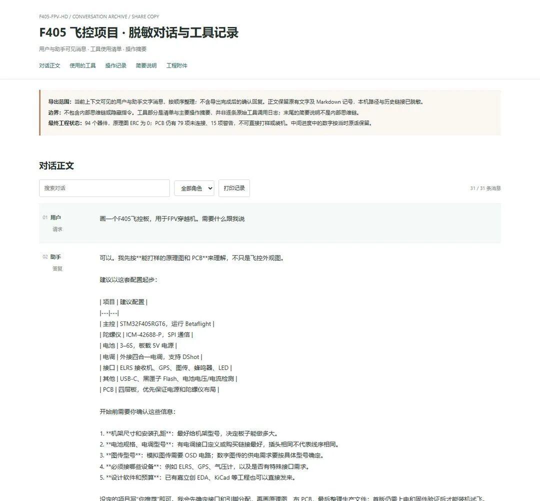
Astra first asked five clarifying questions: frame size and mounting hole spacing, battery and ESC models, analog or digital video, which peripherals must be connected, and which design software to use. The author answered as a typical non-expert client would: “You recommend everything, I don’t have the software either, I just want to test your ability and show a professional what the PCB looks like. Use whatever is universal.”
1. Hardware Design Workflow
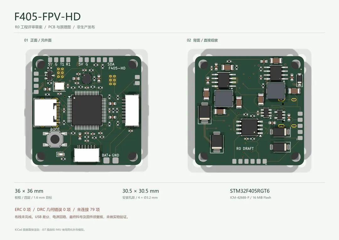
What it ultimately delivered was a browser-openable review page plus a complete editable KiCad project: a main schematic with five functional sub-pages, a six-page schematic PDF, the PCB source file, a 94-component BOM, a pin-by-pin connector pinout table, an MCU pin table, and ERC and DRC check reports. Running the whole flow end to end is what AI does best, so that part is not surprising.
But the summary at the bottom of the overview told a different story: 0 ERC issues, 0 DRC geometry errors, and 79 unconnected items. That means 79 nets were never routed. The workflow is completely correct and the deliverables are thorough, but the design details still need scrutiny.
2. Hardware Architecture and Component Selection
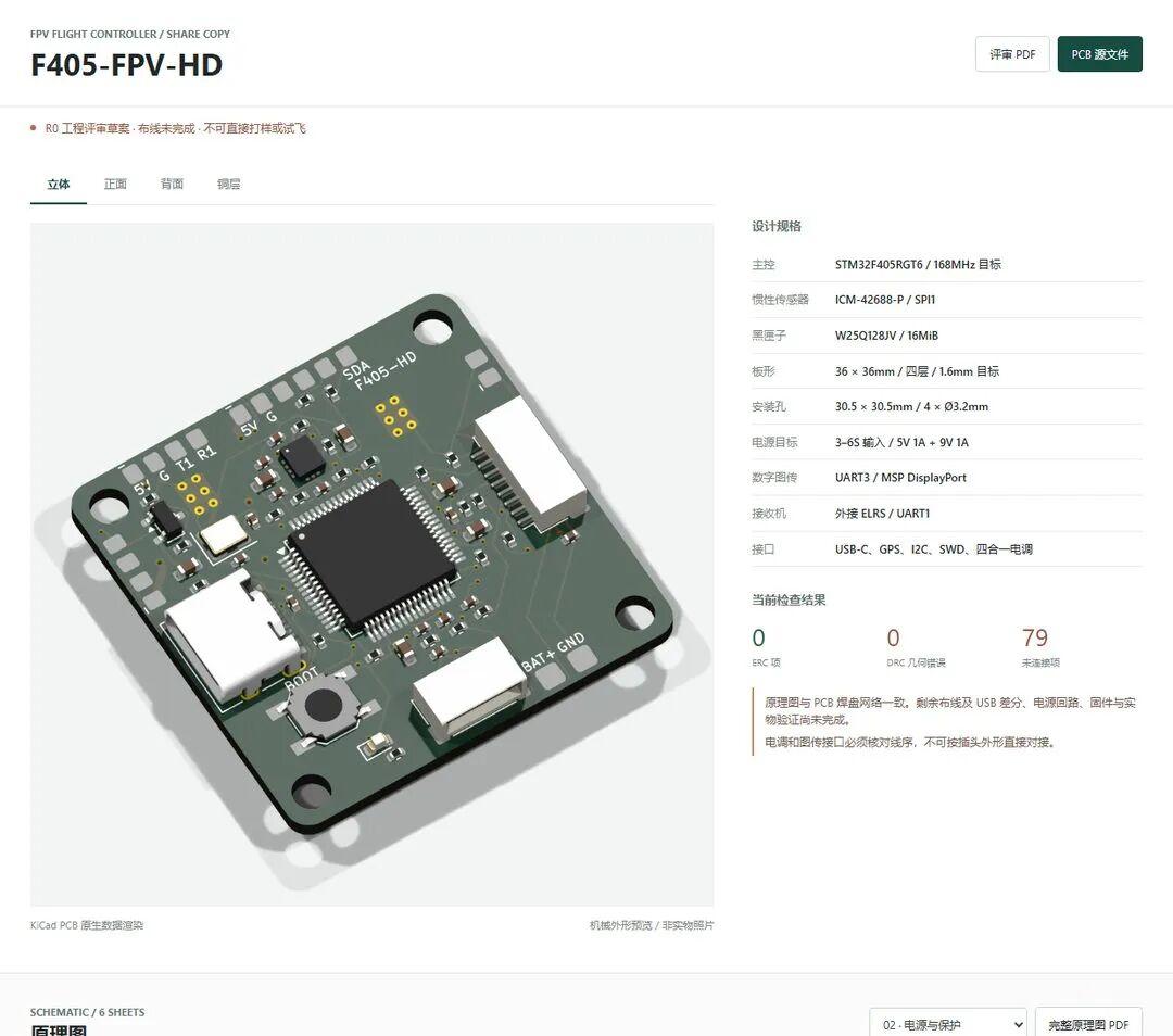
The selection is impressively sensible: an STM32F405RGT6 as the flight controller, an ICM-42688-P gyro, 16 MB of blackbox flash, a USB-C connector, 3–6S battery input, a 36 × 36 mm four-layer board with standard 30.5 mm mounting holes, and an external 4-in-1 ESC. None of the headline choices are wrong.
| Item | Selection |
|---|---|
| MCU | STM32F405RGT6 |
| Gyro / IMU | ICM-42688-P |
| Blackbox storage | 16 MB flash |
| USB | USB-C |
| Battery input | 3–6S |
| Board size / layers | 36 × 36 mm, four layers |
| Mounting holes | 30.5 mm spacing, Ø3.2 mm |
| ESC interface | External 4-in-1 ESC |
3. Schematic Design
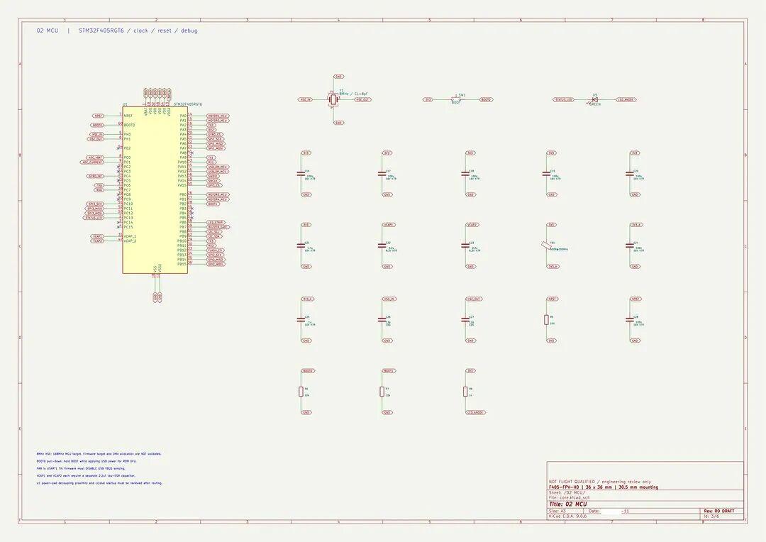
The schematic uses a paged layout, which is a nice touch. This is the MCU page: an 8 MHz crystal with load capacitors labelled 12 pF paired with a CL = 8 pF crystal; VCAP1 and VCAP2 each get a 2.2 µF capacitor with a small annotation reading “never connect in parallel, and never tie to 3V3.” VCAP is the output of the STM32F405’s internal regulator — wire it wrong and the chip simply will not start. Several reminders are written into the drawing corners: PA9 is being used as UART1 TX, so the firmware must disable USB VBUS sensing; the four motor signals are assigned to PA0/PA1 on TIM2 and PB0/PB1 on TIM3, so DShot support has to be verified against DMA availability. Clearly the model picked up real FPV flight controller design conventions from its training data.
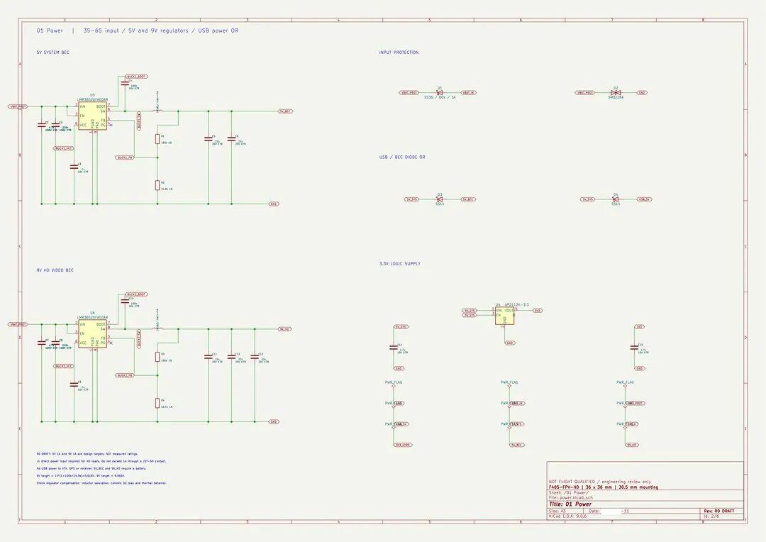
Now the main event: the power design. The title block reads “35–65 V input, 5 V and 9 V dual regulation, USB power.” Both rails use a TI LMR36520 — a 65 V-rated, 2 A synchronous buck — one producing 5 V for logic and peripherals, the other producing 9 V dedicated to the digital video transmitter. The input path has an SS36 Schottky diode for reverse-polarity protection plus an SMBJ28A TVS. Two SS14 diodes OR the USB and battery feeds so battery voltage cannot back-feed into the USB port. The 3.3 V rail is handled by an AP2112K LDO.
To be blunt, those power components are not well chosen. A 6S supply has no need for parts rated to 65 V. The schematic shows the model does follow FPV flight controller practice and its main component selection is commendable, but the power stage carries far too much margin, and SOP-8 packages waste significant PCB area and hurt layout. The design is not wrong, it just has room for optimisation.
4. PCB Layout
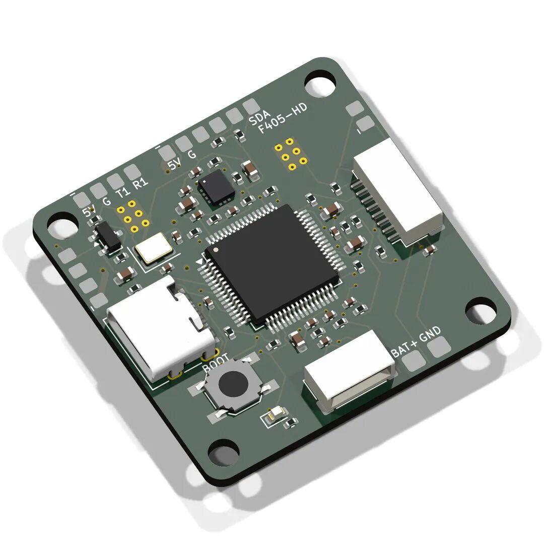
The PCB 3D view is rendered directly from the board data, not a generated illustration. Board thickness is 1.6 mm, four layers, four Ø3.2 mm mounting holes at 30.5 mm spacing, and 2 mm rounded corners — all exactly what FPV flight controllers do. Yet the board also carries a BOOT button, which is genuinely unnecessary, a leftover of redundancy in the schematic stage.
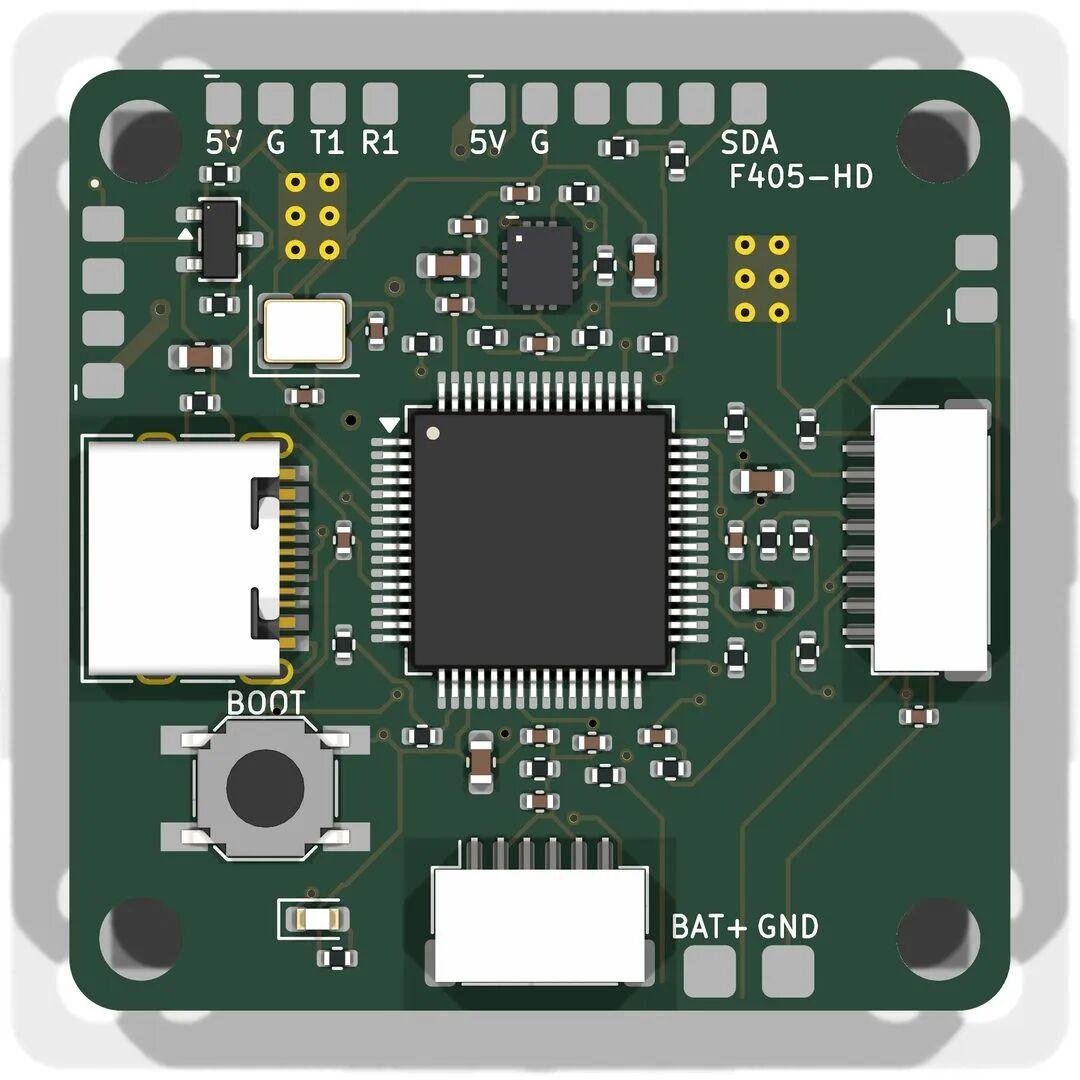
In terms of placement, the central LQFP64 is the STM32F405RGT6 with the gyro above it. USB-C sits on the left; the digital VTX and ELRS receiver JST-SH sockets are packed on the right. That arrangement makes it easy to plug in the USB cable and ribbon cables once the board is installed, which is sensible. Below are the 4-in-1 ESC socket and the battery positive/negative pads, and the top edge carries signal headers for convenient soldering.
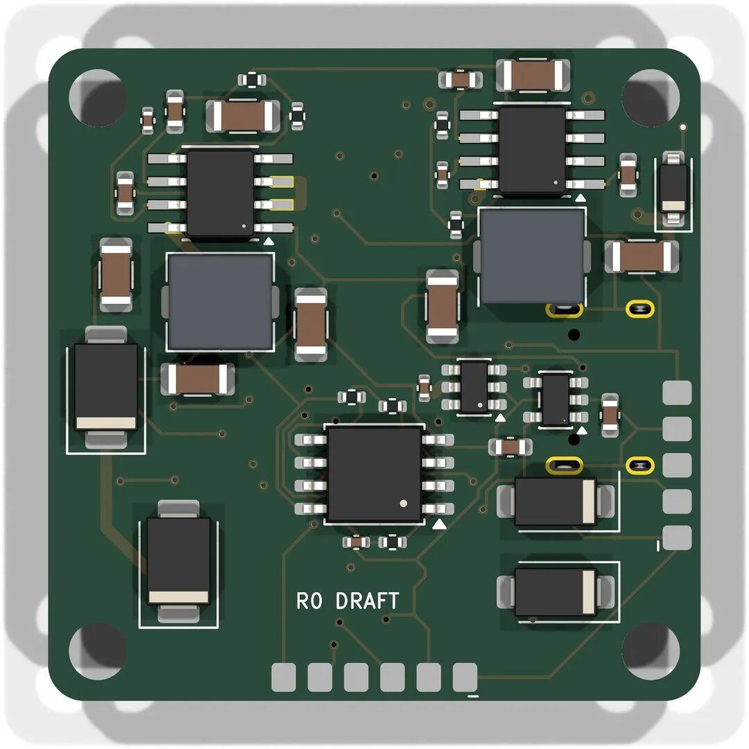
The back side is entirely power. Judging by the inductors, there are two buck circuits, the input protection diodes and TVS, and the blackbox flash. Silkscreen at the bottom reads “R0 DRAFT” — the model’s own version number. Overall the component placement looks fairly reasonable.
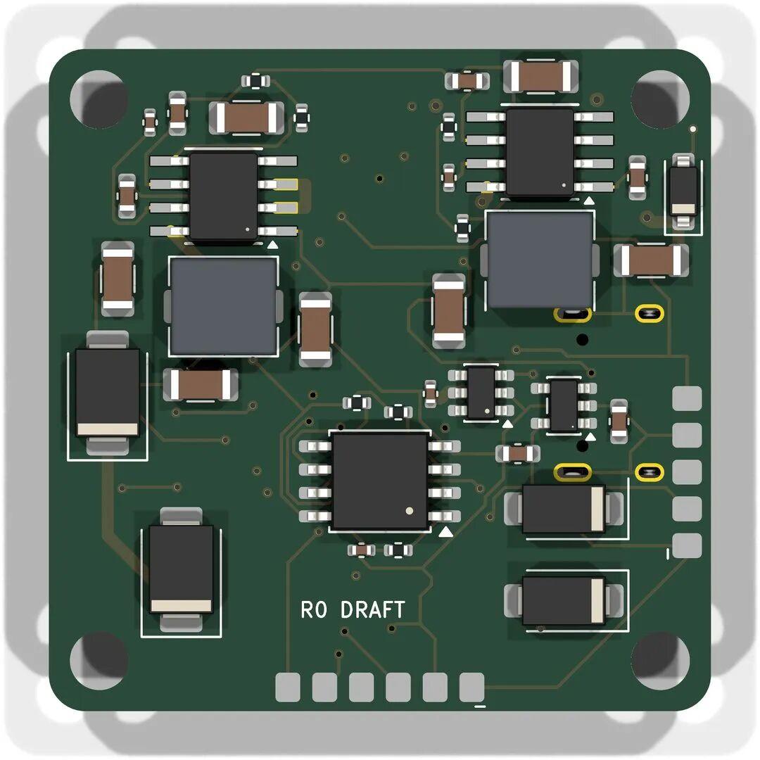
Look carefully at the routing, though, and it is hard to be enthusiastic. Beyond the unconnected signals mentioned earlier, the traces look indistinguishable from an autorouted board. The author’s view is philosophical: if AI can eventually route boards, it will be because it was fed enormous volumes of PCB layout constraints — and if you patiently entered those same constraints into software by hand, it would produce a comparable result. AI replacing manual layout is, at its core, a transfer of design experience and design constraints from the human to the machine.
This exercise is the “Hello World” of board drawing. With a single-sentence prompt, nobody could produce the correct answer. The premise for AI to replace human work is that you must give it enough information: the more complete the information and the prompt, the closer the output gets to what you actually want.
What Comes Next
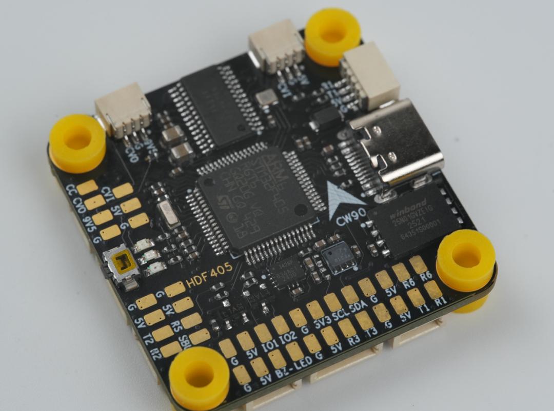
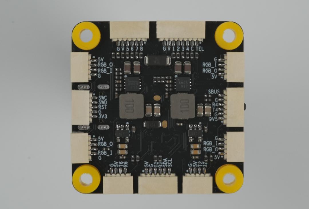
So the plan is to switch approaches: hand over the schematic netlist from a previous flight controller project, add a moderate set of layout and routing constraints, and see how far the model can go. The photos above are of the author’s own board built from that netlist — the back side carries two DC-DC circuits.
Simulating a non-hardware professional handing a hardware brief to AI produced an output with visible flaws, but it must be acknowledged that the model understood the design intent correctly, chose the right design direction and followed the right workflow. With more information and more iterations, it should be capable of producing a board ready for fabrication, and eventually for production. For engineers evaluating this workflow against their own hardware, our open-source flight controller hardware selection guide covers the MCU, IMU and power-stage trade-offs the model was guessing at, the ELRS protocol explainer explains the receiver interface it selected, and our look at AI text-to-CAD part generation shows how far the same idea already goes in mechanical design.
Have questions about this article? Feel free to contact us at [email protected] — we’re happy to help!
Frequently Asked Questions
Can AI actually design a flight controller PCB today?
It can produce the full workflow — schematic, PCB source, BOM and ERC/DRC reports — and its component selection was largely correct. What it cannot yet do reliably is finish the layout: this project ended with 79 unrouted nets and traces comparable to autorouting.
Which components did GPT-6 Astra choose for the F405 board?
An STM32F405RGT6 MCU, an ICM-42688-P gyro, 16 MB blackbox flash, USB-C, 3–6S battery input, a 36 × 36 mm four-layer board with 30.5 mm mounting holes and an external 4-in-1 ESC — all standard, sensible FPV choices.
Why was the power stage considered poorly chosen?
Both rails used TI LMR36520 bucks rated to 65 V for what is only a 6S board, leaving excessive margin. The SOP-8 packages also consume substantial PCB area and complicate placement, even though the circuit itself is functional.
What did the model get right in the schematic?
Several real design conventions: paged schematics, VCAP decoupling warnings, 12 pF load caps for a CL = 8 pF crystal, disabling USB VBUS sensing because PA9 serves as UART1 TX, and motor signals on TIM2 and TIM3 with a DShot DMA check.
What is needed for AI to replace human PCB layout?
Sufficient information and explicit constraints. The author’s thesis is that AI routing works only once it has absorbed vast layout constraint knowledge — and that this is a transfer of design experience from engineer to model, not a replacement for it.
About Aomway
Aomway supplies FPV and UAV hardware, including video transmitters, antennas and link equipment used across drone platforms. Our team follows flight controller board design and AI-assisted engineering closely, and we are happy to discuss hardware choices for FPV and UAV builds.