Key Takeaways
- The -174 dBm/Hz figure is thermal noise power spectral density at the reference temperature of 290 K, derived directly from the Johnson-Nyquist relation N0 = kT.
- Using Boltzmann’s constant k = 1.380649 x 10^-23 J/K at 290 K gives about 4.00 x 10^-21 W/Hz, which converts to -173.98 dBm/Hz — rounded to -174.
- A 300 K approximation yields -173.83 dBm/Hz, a difference of only 0.17 dB that engineers routinely ignore.
- Multiplying by bandwidth is simple addition: the total noise floor equals -174 + 10 log10(B) dBm, so 1 MHz gives -114 dBm and a 20 MHz channel gives -101 dBm.
- Because real receivers add noise figure on top of this floor, every LNA and loss optimisation is an attempt to approach — never beat — this physical limit.
In RF receiver design, link budgeting and noise figure analysis, -174 dBm/Hz is one of those numbers that circulates without explanation. It behaves like a physical barrier marking the thermal noise power floor at room temperature. But where does the value actually come from, and why -174 rather than -170 or -180? The answer starts with Boltzmann’s constant and a short derivation that ties a microscopic physical constant to the system-level specifications engineers use every day.
The Physical Origin: Johnson-Nyquist Noise
Any conductor above absolute zero (0 K) has charge carriers — electrons among them — in constant random thermal motion, which produces random voltage fluctuations across its terminals. This is thermal noise, also called Johnson noise or Nyquist noise. In 1928 Johnson first observed the effect experimentally, and Nyquist soon provided the rigorous theoretical explanation, deriving the single-sideband noise power spectral density:
N0 = k · T
Here k is the Boltzmann constant (1.380649 x 10^-23 J/K) and T is the absolute temperature of the conductor in kelvin. The relation states that thermal noise power spectral density depends only on temperature, not on the material or the resistance value — provided the resistance is far above the scale where quantum effects dominate. This conclusion is a cornerstone of RF noise theory.
Why the Reference Temperature Is 290 K (or 300 K)
To put a number on -174 dBm/Hz, the temperature T must be fixed. RF engineering generally adopts 290 K (about 16.85 degC) as the standard room-temperature reference, the standard noise temperature specified by the ITU and by many RF standards including IEEE. Many engineers simply use 300 K (about 26.85 degC) for quick estimates.
Taking 290 K:
N0 = 1.380649 x 10^-23 x 290 ≈ 4.00 x 10^-21 (W/Hz)
That value is the available noise power generated by thermal motion within each 1 Hz of bandwidth — the maximum deliverable power into a matched load. At 300 K the result is about 4.14 x 10^-21 W/Hz, roughly -173.83 dBm/Hz, just 0.17 dB away from -174 and usually neglected in engineering practice.
From Watts to dBm: The Logarithmic Step
With power spectral density in watts, the next step is conversion to dBm, decibels relative to 1 milliwatt. The conversion is:
PdBm = 10 · log10( PW / 0.001 )
Substituting 4.00 x 10^-21 W:
10 · log10( 4.00 x 10^-21 / 10^-3 ) = 10 · log10( 4.00 x 10^-18 )
= 10 · ( log10 4.00 + log10 10^-18 ) = 10 · ( 0.602 – 18 ) = 10 · ( -17.398 ) ≈ -173.98 dBm/Hz
Rounded up, this yields the familiar -174 dBm/Hz. That simple logarithmic operation is what links a microscopic physical constant to macroscopic system metrics. For a practical look at how the first amplifier stage sets the achievable sensitivity, see our guide on why the LNA is the most critical stage in RF front-end design.
Engineering Meaning: The Sensitivity Ceiling and Bandwidth Scaling
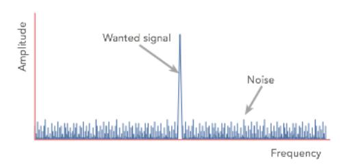
The -174 dBm/Hz figure matters because it defines the minimum detectable signal limit of an ideal receiver at room temperature. Any signal below that power density is buried in thermal noise and cannot be reliably recovered. A real receiver’s own active devices add noise figure (NF), so its noise floor is necessarily higher than -174 dBm/Hz; every engineering effort — optimising the low-noise amplifier, reducing insertion loss — is an attempt to approach that physical limit.
The constant also provides a convenient ruler for bandwidth scaling. For a system bandwidth B in hertz, total thermal noise power is:
Pnoise = -174 + 10 · log10(B) (dBm)
For example, a common 1 MHz bandwidth (10^6 Hz) gives a floor of -174 + 60 = -114 dBm, while a 20 MHz Wi-Fi channel gives -174 + 73 = -101 dBm. This linear addition makes link budgets extremely efficient to compute — see our comparison of link power selection and where bigger transmitters stop helping for how the floor feeds into real range planning.
| Bandwidth | Noise floor |
|---|---|
| 1 Hz | -174 dBm |
| 1 kHz | -144 dBm |
| 1 MHz | -114 dBm |
| 20 MHz | -101 dBm |
| 40 MHz | -98 dBm |
Looking Toward Absolute Zero
Curiously, if the temperature dropped to absolute zero (0 K), thermal noise would vanish (N0 = 0). But as the third law of thermodynamics states, absolute zero cannot be reached in a finite number of steps; and even at extremely low temperatures, non-thermal noise such as quantum shot noise and flicker noise remains. So -174 dBm/Hz is a physical ceiling that can never be broken — a reminder to every RF engineer that we are always working against nature’s most basic fluctuations.
Understanding where -174 comes from is more than memorising a number; it is the entry point to the nature of RF noise. The next time a receiver sensitivity calculation comes up, that terse constant may command a little more respect. For a concrete example of how receiver sensitivity is specified in a real product class, our breakdown of sub-$10 RTL-SDR dongles as full-band receivers shows the trade-offs in practice.
Have questions about this article? Feel free to contact us at [email protected] — we’re happy to help!
Frequently Asked Questions
What exactly is -174 dBm/Hz?
It is the thermal noise power spectral density at the standard reference temperature of 290 K, meaning the noise power available in each 1 Hz of bandwidth. It comes from the Johnson-Nyquist relation N0 = kT.
Why is 290 K used instead of 300 K?
290 K (about 16.85 degC) is the standard noise temperature specified by the ITU and IEEE for RF work. Using 300 K gives -173.83 dBm/Hz, only 0.17 dB different, so the choice rarely matters.
How do I calculate the noise floor for a specific bandwidth?
Add 10 log10(B) to -174. A 1 MHz bandwidth yields -114 dBm, a 20 MHz channel yields -101 dBm, and a 40 MHz channel yields -98 dBm — simple addition makes link budgeting fast.
Can a receiver ever go below -174 dBm/Hz?
No. It is the thermal limit for an ideal receiver at room temperature. Real receivers add noise figure on top, so their floor is always higher, and the goal is only to get as close as possible.
Does the value change with resistance or material?
No. Thermal noise power spectral density depends only on temperature, not on the material or resistor value, as long as the resistance is far above the scale where quantum effects dominate.
About Aomway
Aomway designs and manufactures FPV and UAV video transmitters, antennas and RF link hardware, where receiver sensitivity and noise figure decisions are made daily. Our engineering team works close to these limits, and we are glad to discuss RF link and receiver design questions for drone platforms.