Key Takeaways
- Pairing Codex with a KiCad MCP server turns a design brief — “make a flight controller board for a quadrotor” — into a KiCad project that can be opened, reviewed and edited, rather than a one-off script.
- The reference project is a 40 x 40 mm six-layer flight controller prototype built around an STM32F405, with IMU, barometer, black-box Flash and power regulation on board, plus ESC, receiver, GPS and video transmitter interfaces.
- The delivered engineering data set is six pages of schematics carrying 115 footprints, with Gerber, drill files, BOM, pick-and-place coordinates and a STEP model all exported.
- Setup follows a previously validated toolchain — KiCAD-MCP-Server v2.7.0 for the generic MCP integration — while the completed case was generated with a KiCad 10.99 development build and project-specific extensions.
- The workflow splits cleanly in two: get the MCP connection working first, then drive the design in stages with targeted prompts, checking the schematic and layout between each step.
Getting an AI to design a printed circuit board is easier to reason about when you start from a concrete outcome: turn “make a flight controller for a four-rotor drone” into a KiCad project that can be opened, inspected and revised. That reframing matters, because a PCB produced as a single unreviewable blob of output is of little use to an engineer. What you want is a working project directory — schematics, footprints, a netlist and a board file — that behaves like any other KiCad design.
The case described here ends with a 40 x 40 mm six-layer flight controller research prototype. On board are an STM32F405 microcontroller, an IMU, a barometer, black-box Flash and the power stage, along with interface circuitry for ESCs, a radio receiver, GPS and the video transmitter. The finished project contains six pages of schematics and 115 footprints, and exports the full fabrication and assembly data set: Gerber, drill files, BOM, pick-and-place coordinates and a STEP model for mechanical review.
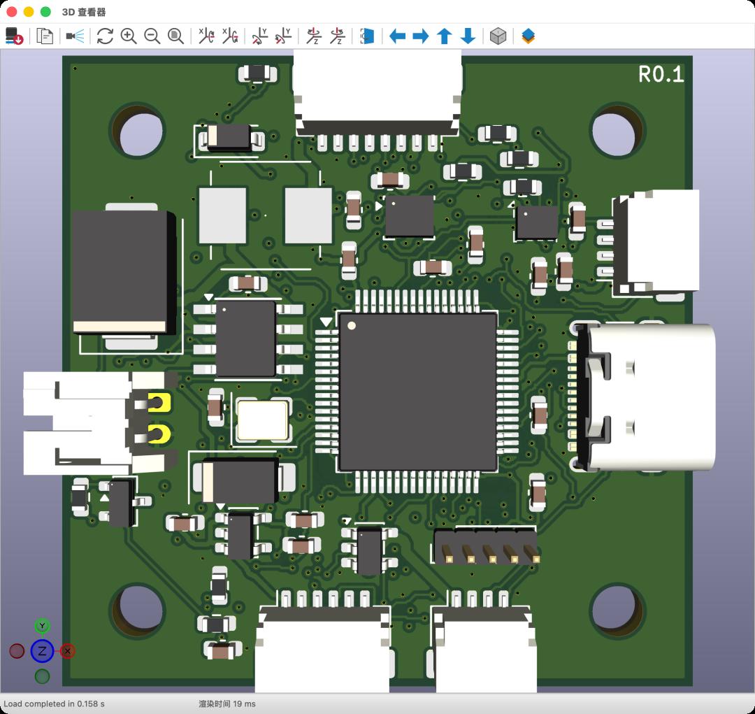 Figure 1: 3D viewer screenshot of the actual project. The L1 inductor in the upper-left area has no precise 3D model and shows only its pads; it still exists in the circuit, the PCB and the BOM.
This article separates installation from design methodology. The generic MCP installation is based on a previously validated toolchain, KiCAD-MCP-Server v2.7.0, while the finished case was produced with a KiCad 10.99 development build plus project-specific extensions. Treat the installation half as the part you can complete today; the design half can be run to whatever depth your tooling actually supports. A complete walkthrough covers the MCP install commands, the staged prompts fed to the AI during PCB design, the six-layer design flow, verification and delivery, and diagrams from the real project.
What a KiCad MCP Server Actually Gives You
An MCP server exposes a tool surface to a language model. Instead of copying files back and forth, the assistant can call functions that read the project state and, where the server allows it, modify the design. For EDA work that means the model can inspect a schematic, enumerate symbols and footprints, check net connectivity, query the board outline and produce reports — all from inside the same conversation that is generating the design intent.
The practical consequence is a feedback loop. The model proposes a circuit, the server reports what the project actually contains, and the model corrects itself against ground truth instead of hallucinating component references. That is the difference between an AI that writes plausible-looking netlist text and one that builds something you can open in KiCad and DRC.
Readers comparing this approach with other AI-assisted board workflows may find our write-up on GPT-6 Astra designing an F405 FPV flight controller board a useful companion, since it covers the same class of board from the generation side. The hardware reasoning behind component choices is covered in our open-source flight controller hardware selection guide.
Installing KiCAD-MCP-Server v2.7.0
Installation is deliberately boring, and it should be. The server runs as a local process and the assistant connects to it over stdio, so the whole integration reduces to three things: a working Python environment, the server package itself, and a correctly formed MCP entry in the client configuration.
Two rules prevent most failures. First, keep the server in its own virtual environment so its dependency versions cannot drift when you update the rest of your tooling. Second, confirm the server starts and responds on its own before you wire it into the assistant — debugging a silent MCP handshake through a chat interface is far harder than testing the server directly.
The case project went further and used a KiCad 10.99 development build with project-specific extensions. That is worth flagging: nightly builds move quickly, and an extension written for one nightly may not load in the next. Pin the KiCad version you validate against, and treat extension compatibility as part of your setup checklist rather than an afterthought.
Prompting Strategy: Stage the Design, Do Not Batch It
The prompt strategy is what separates a usable project from an unusable one. Asking for a complete flight controller in a single instruction produces a flood of output that cannot be reviewed and cannot be corrected in place. Feeding the design in stages keeps every step checkable.
A workable sequence looks like this. First, fix the requirements: board outline, layer count, mounting hole pattern, connector positions and the interfaces the board must expose. Second, generate the power tree and verify the rails before anything else is placed, because a wrong regulator topology invalidates downstream work. Third, add the MCU and its support circuitry — decoupling, crystal, boot and debug — then the sensors, then the interface connectors. Fourth, move to placement and routing, and treat the six-layer stack-up as a constraint the model must respect rather than an implementation detail.
Between each stage, ask the server for a report and read it. Component count, net count, unconnected nets and footprint mismatches tell you whether the previous step actually landed. This is where the project reached six schematics and 115 footprints incrementally, not in one shot.
The Six-Layer Flight Controller Prototype
| Item | Value |
|---|---|
| Board size | 40 x 40 mm |
| Layer count | Six |
| Microcontroller | STM32F405 |
| On-board sensors | IMU, barometer |
| Logging | Black-box Flash |
| Power | On-board regulation stage |
| Interfaces | ESC, receiver, GPS, video transmitter |
| Schematic pages | 6 |
| Footprints | 115 |
| Exports | Gerber, drill, BOM, pick-and-place, STEP |
| Toolchain | KiCAD-MCP-Server v2.7.0; KiCad 10.99 dev build |
Review, Verification and Deliverables
A generated board is only worth shipping if it survives the same checks a hand design would. Run DRC and clear the errors that matter; a clean DRC report with unconnected nets suppressed is not a pass. Cross-check the BOM against the schematic so that reference designators, values and footprints agree, and confirm that every part marked as placed actually appears in the pick-and-place file.
Mechanical review is the step teams skip most often. Exporting STEP and loading it against the frame catches the failures that electrical checks cannot: a connector facing the wrong way, an inductor that overlaps a standoff, a board outline that will not fit the mounting pattern. The reference project illustrates the point neatly — the L1 inductor has no precise 3D model and appears in the viewer as bare pads, yet it is fully present in the circuit, the PCB and the BOM. A 3D model gap is not a design error, but you only know that by checking the underlying data rather than trusting the render.
Finally, treat the deliverable as a data package, not a picture. Gerber and drill files for fabrication, a BOM and pick-and-place file for assembly, and a STEP model for mechanical integration together define a board that can actually be manufactured. Anything less is a drawing. For teams building out the wider avionics, our text-to-CAD generation workflow covers the adjacent problem of turning language into mechanical parts.
Have questions about this article? Feel free to contact us at [email protected] — we’re happy to help!
Frequently Asked Questions
What is a KiCad MCP server used for?
It exposes KiCad project functions to an AI assistant, so the model can inspect schematics, enumerate footprints, check connectivity and generate reports inside the same conversation. That creates a feedback loop where the assistant validates its own output against the real project.
Can an AI design a complete flight controller PCB on its own?
It can produce a complete, reviewable KiCad project when the work is staged and checked at each step. The reference case reached six schematic pages and 115 footprints this way. Human review of power topology, placement and DRC results remains essential.
Why does the board use six layers?
A six-layer stack-up provides dedicated ground and power planes alongside signal layers, which matters on a dense 40 x 40 mm board carrying an STM32F405, sensors and multiple high-speed interface connectors. It keeps return paths controlled and routing manageable.
How long does the MCP setup take?
Installation is short if the environment is prepared: a dedicated virtual environment, the server package, and a correct client configuration entry. The main risk is version drift, especially with KiCad development builds and their project-specific extensions.
What files should a completed PCB design deliver?
Gerber and drill files for fabrication, a BOM and pick-and-place file for assembly, and a STEP model for mechanical integration. A schematic PDF and the KiCad project itself belong in the package too, so the design remains editable.
About Aomway
Aomway designs and manufactures FPV and UAV video transmission hardware, antennas and link equipment for drone platforms from micro builds to long-range systems. As open-source flight controller and PCB design tools evolve, we follow the ecosystem closely and welcome questions about video links and RF hardware for new airframes.