
Key Takeaways
- The package covers a tracked-rotor amphibious UAV: 7 SolidWorks assemblies, 55 part files, one CAD assembly drawing, one SolidWorks engineering drawing, and an ~18-page design manual.
- It ships 3D models, 2D drawings, and written design intent together – a combination that lets you check whether the structure actually matches the stated goals.
- Two independent drive paths share one airframe: a rubber-track chassis on the ground driven by GM6020 motors, and a quadrotor in the air driven by brushless DC motors.
- The load-bearing frame uses carbon-fiber-reinforced polymer, roughly half the density of aluminum, for longer endurance at the same power.
- Open the 3D in SolidWorks 2018+ and the 2D in CAD 2018+. Actual file contents govern over any figure shown here.
A design package for an amphibious tracked-rotor UAV landed on the bench: a folder full of SLDASM and SLDPRT files, a DWG assembly drawing, and a design manual PDF. Normally you would open the top-level assembly first, then work out how the walking and flying systems share one frame. This article follows the order you would actually use at the bench – overall shape and airframe layout first, then the track and rotor support and drive systems, then the manual’s component analysis and innovation claims mapped back onto the model itself.
The distinguishing feature of this package is that it gives you 3D, 2D, and the manual. The structure carries two drive paths at once – ground tracks and aerial rotors – and the classic failure mode when working on a scheme like this is treating “drives on the ground” and “flies in the air” as two unrelated subsystems.
Digital reference material, not a physical product. Contents are governed by the actual files in the archive.

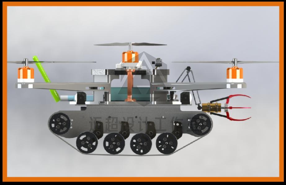
What you are looking at: overall exterior view of the tracked-rotor composite flight vehicle.
First Pass: Read the Overall Shape and Frame Layout
Open the top-level assembly views first. Their job is to establish a sense of scale: how big the frame is, how long the rotor arms are, which side of the body the tracks hang on, and where the landing gear and the gripper sit.
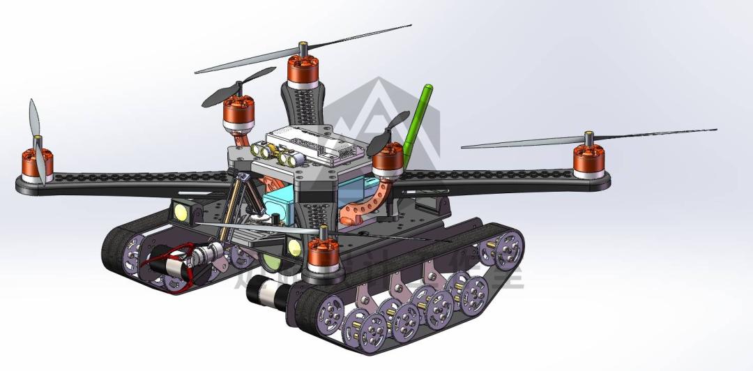
What you are looking at: ground track chassis and aerial rotor structure in one view.
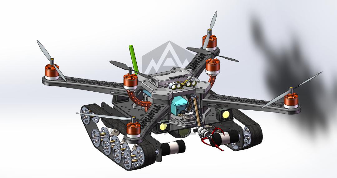
What you are looking at: the platform shown with both ground driving and aerial flight capability.
How the Manual Maps the Whole Machine’s Intent
The design manual PDF runs about 18 pages. It does not simply list parts; it follows a single thread: work overview, design purpose, operating principle, component analysis, product features, innovation points. Read the skeleton first, then go back for detail.
The overview sets the tone. It states plainly that multirotors and ground mobile robots are each mature, but amphibious research is comparatively thin; multirotors with free wheels are awkward to control on the ground, and biomimetic multi-legged designs are too slow. So this scheme integrates a tracked chassis and rotors into a single machine.
The design purpose lists three targeted improvements: controllable speed for forward, backward, and lateral movement; the ability to stop quickly in the air; and ground motion that is fast rather than a “multi-legged crawl.” That is what decides why you see a rubber-track chassis rather than wheels or legs.
The operating principle separates the two paths. The aerial path handles flight, turning, and hovering via rotor drive. The ground path uses tracks on varying terrain, with a gripper handling grasping, dragging, and moving. The body also mentions adding a searchlight and infrared night-vision equipment for night or poor-light conditions.
The component analysis is the block diagram, split into four groups: support components, drive components (walking and flight devices), working components (imaging, photography, and mapping assembly plus gripper), and energy and control components. This maps one-to-one onto the 3D assembly later, and walking the four groups is the fastest way to identify parts.
Six points from the manual worth checking against the model one by one:
- The machine is positioned as a “new multi-purpose amphibious unmanned aerial vehicle” covering aerial photography, logistics, geographic surveying, biological monitoring, environmental protection, disaster rescue, precision agriculture, security, meteorology, and dual civil-military use. That is what justifies having both tracks and rotors.
- On materials and power, support parts use carbon-fiber-reinforced resin composite (density a little over half that of aluminum), the tracks are driven by GM6020 motors, and the rotors by high-performance brushless DC motors. That is what makes the frame a lightweight skeleton rather than a conventional metal one.
- Drive splits into two independent paths: a rubber-track chassis on the ground and a multirotor in the air, so the assembly shows two complete component sets – track drive and flight drive.
- Working components combine an imaging, photography, and mapping assembly with a gripper, so the model shows camera mounts, a laser mapping position, and a grasping mechanism together.
- Energy and control use high-rate lithium polymer batteries, emphasizing specific energy, miniaturization, ultra-thin construction, weight reduction, and safety – which is what sets the packaging space for the battery bay and electronics.
General Assembly Layout
What to look at: this assembly puts the whole machine in one frame – rotors on top, tracks on both sides, gripper at the belly. How it connects: it corresponds to the manual’s component analysis overview. The rotors are the flight drive device, the tracks are the walking drive device, and the gripper is the working component.
The perforated plate at the center is a support component, carrying the flight controller, motors, ESCs, battery, and every other load. What to watch for: identify the relative positions of the center plate and the four rotor arms first, then descend separately to the track sides and the belly gripper. Do not rush to open individual part files at this stage – matching the sub-assembly nodes in the tree is enough.
Tracks and Rotors in the Same Frame
What to look at: this view puts the track chassis and the quadrotor at the same angle, showing how the frame balances between the two paths. How it connects: the tracks hang on the left and right sides of the body while the rotor arms extend above the frame. The battery bay and flight controller layer in the middle are sandwiched between the track support arms.
What to watch for: before modifying the model, confirm where track tension is adjusted and whether the rotor arms interfere with the track support arms. The manual gives intent rather than numbers here; take the actual dimensions from the model in the archive.
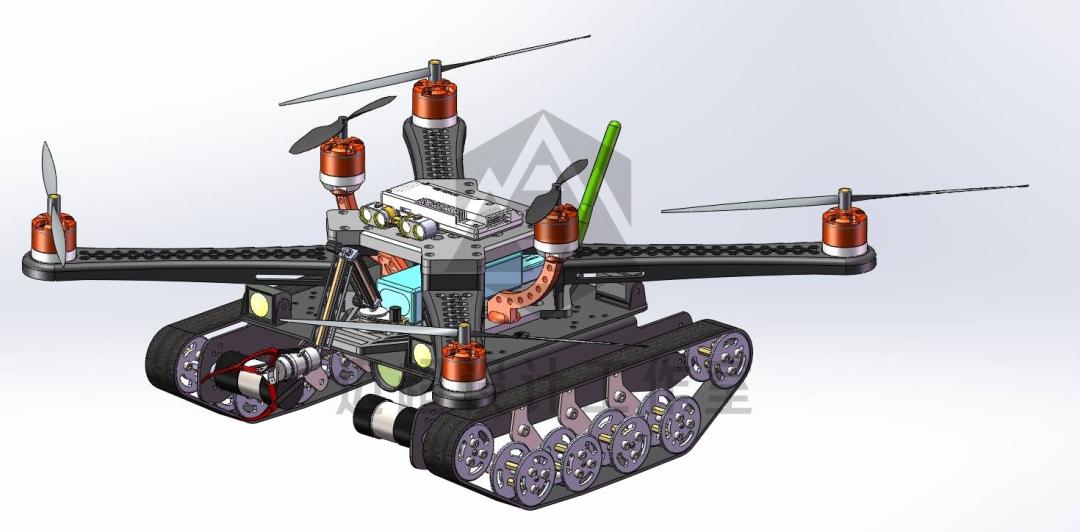
What you are looking at: ground track chassis and aerial rotor structure in one view.
Frame and Landing Gear
What to look at: another angle on the complete machine, focused on how the frame is layered and where the belly landing and grasping zone sits. How it connects: support components use carbon-fiber-reinforced resin composite for the frame panels, carrying the flight controller, motors, ESCs, and battery. The manual’s wording is that the density is “a little over half that of aluminum, enabling longer endurance at the same power.”
What to watch for: open the assembly tree and find the support or frame sub-assembly first, then look inside its part files to see which are panels and which are fasteners. Lightweight design usually means thin walls, so take care about where to add local reinforcement when modifying.
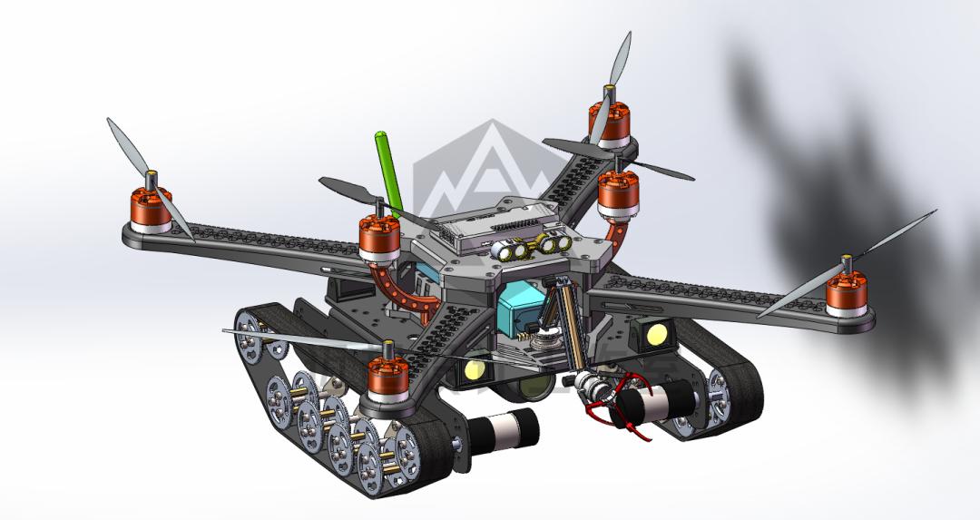
What you are looking at: the airframe with both ground driving and aerial flight capability.
Working Components
What to look at: an exploded view of the working components block, showing how the motor, camera mount, sensor modules, and grasping mechanism fit together. How it connects: the manual describes working components as an imaging, photography, and mapping assembly combined with a gripper, which is exactly this group of sensing and grasping parts.
The camera section handles close and long-range high-definition capture and obtains three-dimensional coordinates of the target through laser mapping; the gripper handles grasping, dragging, and moving. What to watch for: sensor mounting positions are easy to overlook when working on a mechanism scheme. Confirm the gripper arm’s rotation axis in the assembly first, then check its clearance against the track support arm.
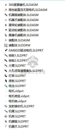
What you are looking at: the gripper assembly and its part file list.
Multi-Light and Sensor Module
What to look at: two four-lamp lighting groups and a red sensor module under the belly – key components for night operation and target recognition. How it connects: the manual states that a searchlight and infrared night-vision equipment are added to the body so missions can be completed at night and in poor light. These two lamp groups and the red sensor are the physical counterpart.
What to watch for: in the assembly this usually falls under the sensor sub-assembly of the working components. When analyzing lighting scenarios, start from that sub-assembly and trace back its routing and power supply.
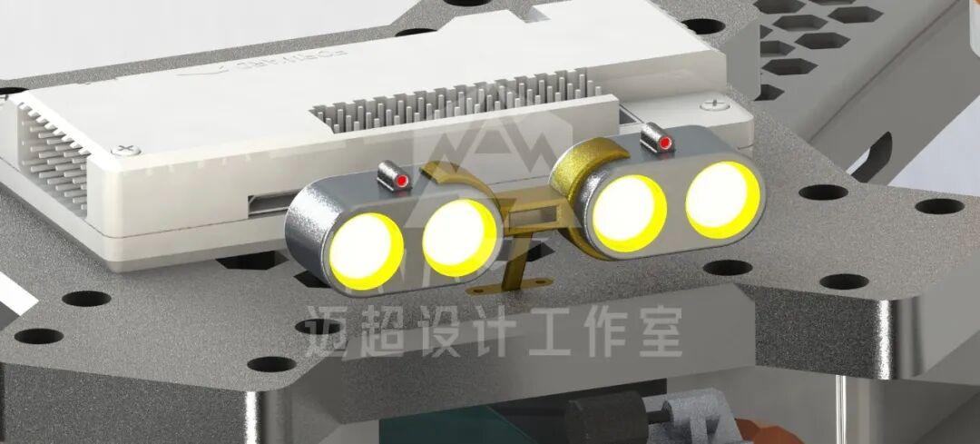
What you are looking at: multi-light sensor module assembly detail.
Track Chassis and Robotic Arm
What to look at: the track chassis combined with the red grasping mechanism, showing the relative positions of the tracks, drive wheels, road wheels, and the robotic arm. How it connects: this corresponds to the walking drive device and the gripper in the working components. GM6020 motors drive the tracks, and the gripper hangs at the belly to grasp. What to watch for: when simulating ground motion, prioritize track tension, the axis line from drive wheel to road wheels, and clearance between the arm root and the track support arm.
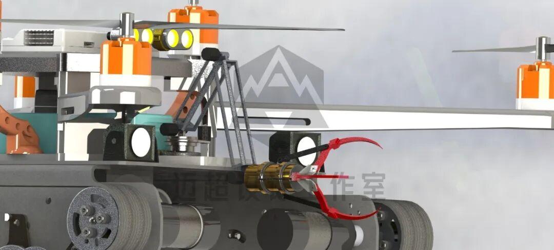
What you are looking at: the tracked drone’s robotic arm assembly.
Power Distribution
What to look at: this view focuses on where the powered components sit. Rotor motors are at the ends of the four arms, track motors are on both sides of the chassis, and the battery bay and electronics are concentrated at the center of the frame. How it connects: the manual states that track drive uses GM6020 motors and rotor drive uses high-performance brushless DC motors, with high-rate lithium polymer batteries for energy.
The three groups are distributed in the model as a central battery bay, four rotor arms, and track motors on both sides. What to watch for: when estimating the center of mass, treat the central battery bay as the main mass block, then add the quadrotor and the two track motors as distributed masses.
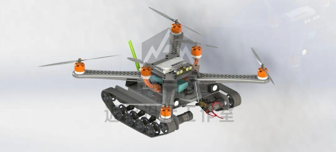
What you are looking at: airframe structure and power distribution layout.
Two-Dimensional General Drawing
What to look at: the general assembly engineering drawing, containing multiple views and a 3D view, corresponding to the CAD drawing and SolidWorks engineering drawing in the archive. How it connects: the engineering drawing compresses the 3D back into 2D so you can read proportions, symmetry, and assembly relationships. Combined with the manual’s component analysis, each callout can be traced back to its part quickly.
What to watch for: the track tensioning mechanism and the full detail of the sensor modules are not visible in 2D and have to be read in 3D. Specific dimension values are governed by the engineering drawing in the archive.
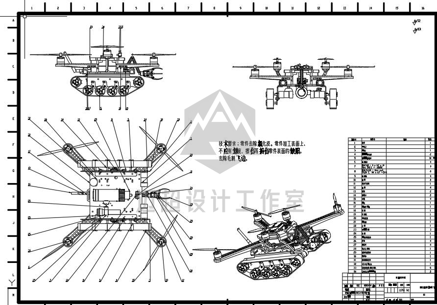
What you are looking at: a drawing with multiple views plus a 3D view.
Airframe Part Composition
What to look at: opening the part layer reveals support plates, reinforcing ribs, various fasteners, long screw bosses, and motor mounts – essentially a group portrait at the part level. How it connects: support components consist of several layers of panels and fasteners; track components consist of drive wheels, road wheels, track links, and tensioning parts; rotor components consist of motor mounts, blade grips, and blades.
The 55 part files break down roughly into those three families. What to watch for: do not model every part individually. Go through by family first, then open the detail parts you care about. Each part’s actual content is governed by the file in the archive.
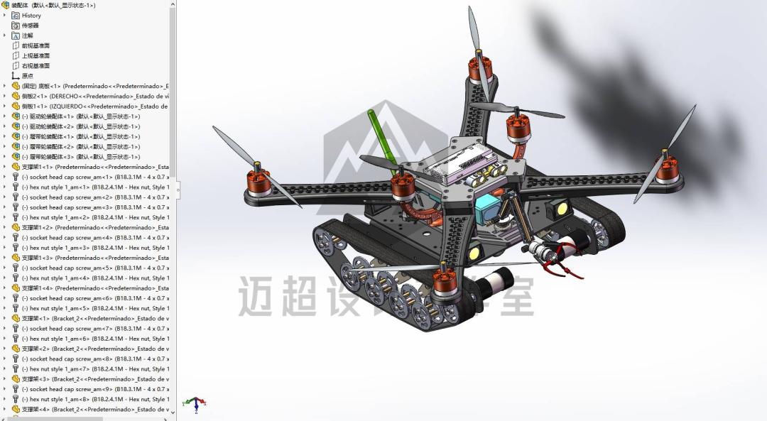
What you are looking at: airframe structure and constituent part families.
Running Gear Close-Up
What to look at: detail views of the track chassis and the landing section. How it connects: it corresponds to the walking device sub-assembly, showing the arrangement of track links, drive wheels, and road wheels plus the landing section. What to watch for: whether the landing section doubles as the gripper root determines the routing space at the belly. For grasping posture simulation, confirm the landing section height first.
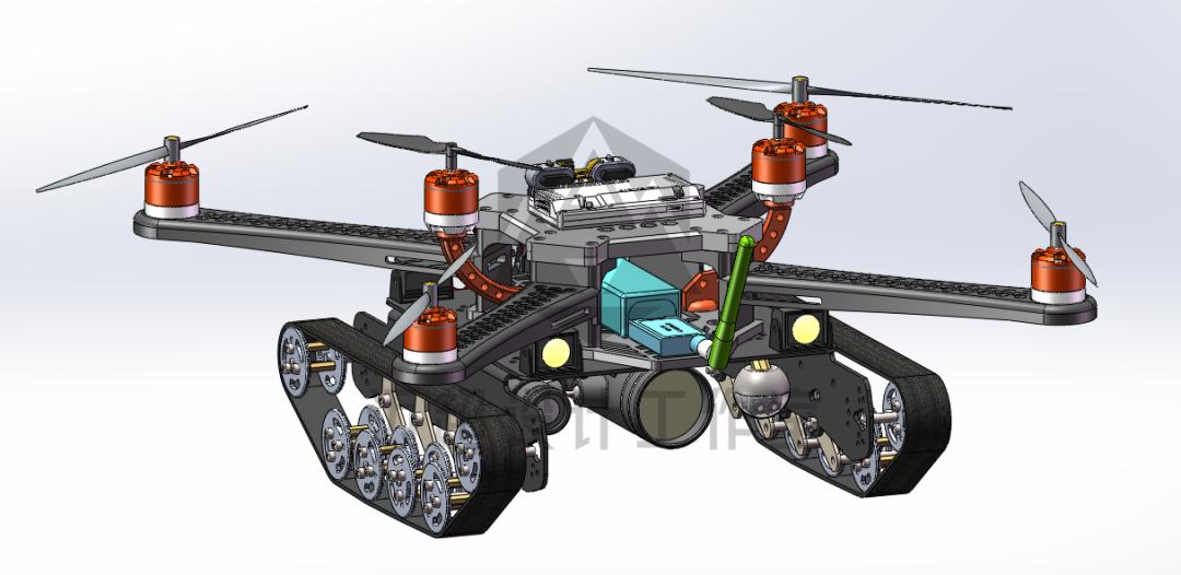
What you are looking at: airframe structure and running gear.
Quadrotor Layout and Arm Mounting Positions
What to look at: the quadrotor layout plus the robotic arm mounting positions, with the red grasping parts under the belly and the four rotor arms clearly identifiable. How it connects: this view combines the rotor flight sub-assembly with the working components, showing directly how flight and grasping share one frame. What to watch for: for coupled hover-and-grasp simulation, confirm the arm root’s rotational degrees of freedom first, then check whether it interferes with the tracks below.
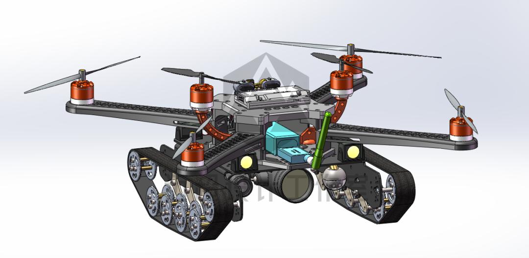
What you are looking at: the tracked quadrotor drone 3D model.
An Alternative View
What to look at: the complete machine with wheeled landing gear, contrasted against the tracked version, useful for comparing schemes with different ground adaptability. How it connects: read it side by side with the tracked view and consider the possibility that the ground locomotion component is a replaceable module sharing the same rotors and frame. What to watch for: the specific differences between this landing gear and the tracked version are governed by the model in the archive – do not infer dimensions from the figure.
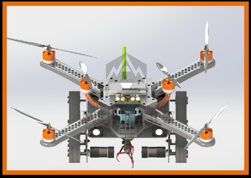
What you are looking at: quadrotor 3D general assembly model.
What Is Actually in the Package
| Item | Contents |
|---|---|
| 3D models | 7 SolidWorks assemblies, 55 part files (SLDASM / SLDPRT) |
| 2D drawings | 1 CAD assembly drawing, 1 SolidWorks engineering drawing |
| Documentation | ~18-page design manual (overview, purpose, principle, component analysis, features, innovations) |
| Extras | 1 general-purpose 3D model plus several preview images |
| Software | SolidWorks 2018+ for 3D, CAD 2018+ for 2D |
Exact versions and opening instructions are governed by the actual files in the archive.
What It Is Good For
Scheme practice: treat it as a reference sample that has structure, drawings, and documentation all present. The three-in-one architecture – tracks, rotors, and gripper – is well suited to comparing schemes, looking at component layering, routing space, and the trade-offs of sharing a transmission frame.
Self-study: use it to practice the disassembly path from assembly tree to sub-assembly to key part. The manual’s four-part component analysis (support, drive, working, energy) works well as a scaffold for reading the drawings.
Digital design reference material, not a physical product. Contents are governed by the actual files in the archive.
Have questions about this article? Feel free to contact us at [email protected] — we’re happy to help!
Frequently Asked Questions
What files are included in the amphibious drone design package?
Seven SolidWorks assemblies and 55 part files, one CAD assembly drawing, one SolidWorks engineering drawing, and an approximately 18-page design manual, plus a general-purpose 3D model and preview images.
What software do I need to open these files?
SolidWorks 2018 or newer for the 3D assemblies and part files, and CAD 2018 or newer for the two-dimensional drawings. Exact version requirements are governed by the files in the archive.
Why does this design use tracks instead of wheels or legs?
The manual argues that multirotors with free wheels are awkward to control on the ground while biomimetic multi-legged designs are too slow. A rubber-track chassis gives faster, more controllable ground movement.
How are the track and rotor drive systems kept separate?
They are two independent paths on one airframe. GM6020 motors drive the rubber tracks for ground movement, while high-performance brushless DC motors drive the quadrotor for flight, turning, and hovering.
Is the design package a physical product?
No. It is digital reference material – 3D models, 2D drawings, and a design manual. All contents are governed by the actual files in the archive rather than by figures shown in any article.
About Aomway
Aomway is a technology company specializing in drone and FPV equipment, publishing in-depth analyses of motor control, embedded hardware, and open-source robotics projects. With over 15 years of industry experience, Aomway covers the full spectrum from flight controllers and FPV goggles to thermal imaging cameras and long-range datalinks for the global drone community.